Note: Descriptions are shown in the official language in which they were submitted.
CA 03237703 2024-05-06
WO 2023/086294 PCT/US2022/049113
HOT-RUNNER ASSEMBLY WITH COMPACT ELECTRIC ACTUATOR
CROSS-REFERENCE TO RELATED APPLICATIONS
[0001] This application claims priority to U.S. Application No.
17/454,670, filed on
November 12, 2021, which is hereby incorporated by reference in its entirety.
FIELD OF THE DISCLOSURE
[0002] This disclosure pertains to a hot-runner injection molding
apparatus having an
actuator.
BACKGROUND OF THE DISCLOSURE
[0003] In a hot-runner injection molding apparatus, the liquid resin
(molten plastic) is
maintained in a molten state within channels defined in a heated manifold. The
channels convey
the molten plastic material from an injection molding machine to one or more
nozzles that
convey the molten plastic to at least one mold cavity via gates defined at an
interface between
the nozzle and the mold cavity. After the mold cavity is filled, only the mold
cavity is cooled
to allow removal of a solid molded part. The resin in the manifold channels
and nozzles are
maintained at a temperature sufficient to keep the plastic in a liquid state,
thus reducing cycle
time and waste as compared with cold runner injection molding apparatuses,
wherein the resin
conveying channels are defined within the mold plates.
[0004] Because of the susceptibility of electric actuators to degradation
and failure
when exposed to the high temperatures needed at the hot-runner manifold,
hydraulic or
pneumatic actuators are typically employed in hot-runner injection molding
apparatus to control
the flow of molten resin into the mold cavity (or cavities). In these hot-
runner injection molding
apparatuses employing electric actuators, the electric actuators are
positioned remotely from the
manifold and/or are provided with external cooling means (e.g., a cooled plate
between the
1
CA 03237703 2024-05-06
WO 2023/086294 PCT/US2022/049113
manifold and actuator), adding considerable complexity and expense as compared
with the more
conventionally used pneumatic or hydraulic actuators.
[0005] Despite these generally recognized disadvantages with electric
actuators, they
also have advantages, including the ability to more precisely control valve
pin movement
and positioning, which in turn can have associated advantages pertaining to
part quality and
production efficiency.
[0006] Electric actuators for controlling the valve pin positions of
injection molding
systems offer significant advantages in certain applications, including
cleaner operation by
avoiding the inevitable leaks that occur with hydraulic actuators, and more
precise control over
valve pin position and flow of resin into the mold cavities. Cleanliness is an
important
consideration and advantage in the manufacture of injection molded items used
for
pharmaceutical and medical products. Precise control of melted resin flowing
into a mold cavity
can also be extremely beneficial to avoid or minimize imperfections, such as
flow lines (wavy
patterns or discolorations) caused by more rapid cooling in thinner sections
of the molded part,
and knit lines (where two or more flows into a mold meet). These
imperfections, which do
not typically affect functionality or integrity, but can cause undesirable or
even unacceptable
aesthetics.
[0007] While electric actuators have advantages with respect to flow
control and
cleanliness, conventional electric actuators used for injection molding
systems are bulkier than
the hydraulic actuators currently used in most injection molding systems,
which have a
transmission for converting rotary motion of the output shaft of the electric
motor into linear
movement to facilitate linear movement of the valve pin along a longitudinal
axis of a nozzle
directing resin flow into the mold. In conventional electric actuators used
for injection
molding, the transmission is external to the motor assembly and is often
located in a housing
separate from the motor housing. As a result, assembly of the injection
molding apparatus
becomes more cumbersome, and the transmission occupies volume that limits or
restricts
flexibility in actuator positioning, and consequently, flexibility in the
design of the molding
apparatus.
2
CA 03237703 2024-05-06
WO 2023/086294 PCT/US2022/049113
SUMMARY OF THE DISCLOSURE
[0008] Described herein are injection molding systems employing a compact
electric
motor valve actuator in which the valve pin for controlling resin flow to the
mold cavity is
configured to directly or indirectly couple the head of the valve pin to a
drive shaft located
within a space defined within the internal boundaries (or surfaces) of the
rotor of the electric
motor.
[0009] In certain aspects of the disclosure, the actuator can be an
electric, pneumatic or
hydraulic actuator including a housing or actuator body having an integral
cooling block or plate
with internal conduits for circulating a coolant liquid (e.g., water).
[0010] In other aspects, the actuator can be an electric, pneumatic or
hydraulic actuator
that is supported on an insulating member that positions the actuator so that
there is a gap
between a surface of the actuator housing facing the hot-runner manifold and
the surface of
the insulating support plate facing the actuator housing.
[0011] In a further aspect of the disclosure, a compact contactless linear
position sensor
is located in the actuator housing, and configured to precisely monitor the
position of the valve
pin to facilitate precise control of resin flow to a mold cavity. The actuator
can be an electric,
pneumatic or hydraulic actuator.
BRIEF DESCRIPTION OF THE DRAWINGS
[0012] Figure 1 is an elevational cross-section of an apparatus in
accordance with this
disclosure.
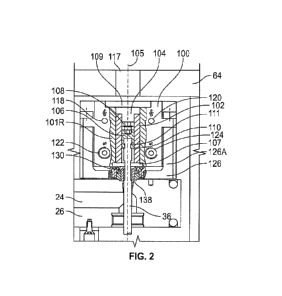
[0013] Figure 2 is an enlarged view of the actuator and a portion of the
hot-runner
manifold on which the actuator is supported.
[0014] Figure 3 is a perspective view of an actuator support and mechanism
for fixing the
valve pin to a linear drive shaft.
3
CA 03237703 2024-05-06
WO 2023/086294 PCT/US2022/049113
[0015] Figure 4 is an enlarged cross-sectional view of an alternate
embodiment in which
the valve pin is indirectly coupled to the actuator drive shaft via a valve
pin extension.
[0016] Figure 5 is a perspective view of the actuator.
[0017] Figure 6 is a cross-sectional perspective showing a contactless
linear position
sensor mounted within the actuator body to provide a compact actuator assembly
that facilitates
precise flow control.
[0018] Figures 7A-7D illustrate a procedure for securing an anti-rotation
device or part to
a support plate mounted on a hot-runner manifold to prevent rotation of a
valve pin.
[0019] Figure 7E illustrates an alternative non-anti-rotation
configuration.
[0020] Figure 8 is a partial cross-sectional view of an actuator mounting
assembly that
provides improved heat management.
DETAILED DESCRIPTION
[0021] Shown in Figure 1 is a hot-runner assembly 10 for use in delivering
liquid resin
(typically a molten thermoplastic composition) from an injection molding
machine (not shown)
to a mold cavity 12 defined by mold plates 14, 16. The resin flows from the
injection molding
machine into a channel 18 disposed in a sprue bushing 20 heated by electrical
resistance heating
element 22 and is distributed through manifold channels 24 defined in heated
(or heatable)
manifold 26. The heated manifold is provided with electrical resistance
heating elements 28
capable of maintaining the resin at a desired temperature that facilitates
flow. The resin flows
from the manifold channels 24 into an annular space 30 defined between
internal walls 32 of
nozzles 34 and a valve pin 36 that is linearly movable within nozzle 34 along
a longitudinal
axis of the nozzle between an open position (shown for the nozzle on the left
in Figure 1) and a
closed position (shown for the nozzle on the right in Figure 1). When the
valve pin 36 is in the
open position, liquid resin (e.g., molten thermoplastic) flows into mold
cavity 12. Nozzles 34
are maintained at a temperature sufficient to keep the resin in a liquid
(flowable) state by
electrical resistance heating elements 38. Nozzles 34 can be provided with
external threads 40
on the inlet end of the nozzle which engage internal threads of a bore through
the bottom of
4
CA 03237703 2024-05-06
WO 2023/086294 PCT/US2022/049113
manifold 26 to provide a fluid-tight seal. The mold can define a single cavity
or multiple
cavities, and each cavity can be supplied with resin from a single nozzle or
multiple nozzles.
[0022] The position and rate of movement of valve pins 36 are controlled by
an actuator
100. Actuator 100 includes a body and/or housing for an electric motor 101 and
converts
rotational movement of the electric motor into linear movement (up and down in
Figure 2) of a
drive shaft 102 (e.g., an externally threaded shaft having a cylindrical
longitudinal bore
inside), which in the illustrated example has an elongate internally threaded
bore 104 going
through the whole length of the drive shaft Rotation of rotor 101R relative to
stator 101S
around axis 105 (Figure 6) can be converted to linear movement of drive shaft
102 such as by
providing threaded structure on the rotor that directly or indirectly (e.g.,
planetary roller screw
mechanism) engages external threads on drive shaft 102. The extent of travel
of drive shaft 102
can be limited to the confines of the body of actuator 100. Bore 104 has a
central axis 105
coincident with the central axis of pin 36 and nozzle 34. The body and/or
housing of actuator
100 has a bottom opening 107 and a top opening 109 that allows access to
threaded bore 104 to
allow an externally threaded valve pin nut 106 to be threaded into bore 104
from both directions.
A lock nut 108 can be threaded into bore 104 from the top opening to lock the
position of
valve pin nut 106 and valve pin 36 after it has been adjusted. A lower end of
valve pin nut 106
has an inwardly projecting semi-circumferential rim 111 that engages a
circumferential groove
112 at an upper end of valve pin 36 to secure valve pin 36 to valve pin nut
106. An opening in
the rim allows the valve pin 36 to be inserted into valve pin nut 106. The
threaded connection
between valve pin nut 106 and drive shaft 102 can be replaced with a fixed or
other connection
between the drive shaft 102 and valve pin nut 106, although this would
eliminate the possibility
of manually adjusting the valve pin position (as described below).
[0023] Notably, the pin head 110 is coupled to valve pin nut 106, which is
fixed within
elongated internally threaded bore 104 of drive shaft 102, such that the head
110 of valve pin 36
is directly or indirectly coupled to the drive shaft within a cylindrical
space defined by the
interior radial boundaries of the rotor and opposite ends of the rotor.
[0024] Valve pin nut 106 can have a tool-head engagement structure 114 that
can be
engaged by a tool, such as an Allen wrench to allow manual adjustment of the
position of valve
CA 03237703 2024-05-06
WO 2023/086294 PCT/US2022/049113
pin nut 106 and pin 36. Similarly, lock nut 108 has a tool-head engagement
structure and bore
116 to allow tightening of lock nut 108 against valve pin nut 106 using a tool
such as an Allen
wrench to keep the valve pin nut 106 from moving or rotating. In the
illustrated embodiment,
engagement structures 114 and 116 are hexagonal sockets. However, other shapes
or tool-
engagement means are possible. Top plate 64 can be provided with openings or
bores 117 to
allow access to tool engagement structure (e.g., sockets 114, 116) to
facilitate manual
adjustment of the valve pin position without removal of plate 64 or
disassembly of hot-runner
assembly 10. This arrangement can be employed with an electric, pneumatic or
hydraulic
actuator.
[0025] Electrical connectors 118, 120 are provided for powering and
controlling the
electric motor, and/or to power and receive signals from an encoder that
tracks drive shaft
position.
[0026] Actuator 100 can be provided with an integral cooling plate having a
coolant
inlet port 122 and a coolant outlet port 124 to allow a coolant (e.g., chilled
water or oil) to be
circulated through the body and/or housing of the actuator to protect the
motor against
degradation or failure caused by overheating. Integration of the cooling block
into the actuator
body also simplifies assembly and disassembly of an injection molding
apparatus.
[0027] Actuator 100 can be supported on an insulating support plate 126
(see Figure 3).
Support plate 126 can, and preferably does, have a relatively low thermal
conductivity. Preferred
materials for support plate 126 are stainless steel and titanium or other
material having a thermal
conductivity equal to or less than the thermal conductivity of titanium.
Support plate 126 can
be releasably secured to manifold 26, such as with screws or bolts (not
shown).
[0028] When assembled, the upper end of valve pin 36 extends into bore 104
through
openings in manifold 26, support plate 126 and the body or housing of actuator
100 to provide
a vertically compact design for mold 10.
[0029] Optionally, an anti-rotation disc or guide 130 (Figures 7A-7D) can
be
releasably secured to support plate 126 with bolts 132. Part 130 has an
aperture (e.g., keyhole
design) 134 for passage of valve pin 36. Aperture 134 has a shape configured
to engage a section
of valve pin 36 having a non-circular profile (e.g., parallel flats that fit
the key hole) to prevent
6
CA 03237703 2024-05-06
WO 2023/086294 PCT/US2022/049113
rotation of the pin around the longitudinal axis of the pin 36 and nozzle 34.
In the illustrated
embodiment, the non-circular profile includes two opposing flat or planar
surfaces
136 (one of which is shown in Figure 3). While flat surfaces 136 are engaged
by
straight edges 134 of an aperture through the anti-rotation part 130 of the
illustrated
embodiment, other anti-rotational means can be provided, such as splines,
grooves,
and other structures that can prevent rotation of valve pin 36.
[0030] The procedure of securing anti-rotation part 130 to support plate
126
and engaging surfaces of part 130 with surfaces of pin 36 to prevent rotation
of pin
36 is illustrated in Figures 7A-7D. The first step involves lowering part 130
onto
support plate 126 with pin 36 extending through an enlarged section of
aperture 134
of part 130 (Figure 7A). The next step involves sliding part 130 in the
direction
indicated by arrow 170 in Figure 7A with the flat surfaces 135 of aperture 134
engaging the flat surfaces 136 of pin 36 (as shown in Figure 7B). It may be
necessary to rotate part 130 and pin 36 together while in the conformation
shown
in Figure 7B so that fastener openings 172 through part 130 are aligned with
threaded bores 174 in the upper surface of support plate 126. Then fasteners
132
are aligned with openings 172 (Figure 7C) and threaded into bores 174 (Figure
7D).
[0031] Manifold 26 and actuators 100 are located in a space generally
bounded by a top
mold plate 64 and an intermediate mold plate 66.
[0032] Assembly 10 can also include various lower support elements 68,
dowels 70, and
upper support elements 72 for facilitating proper alignment and spacing of the
components of
the assembly.
[0033] A pin seal 138 prevents liquid resin from leaking upwardly from
channel 24 of
manifold 26.
[0034] The disclosed apparatus allows adjustment of the valve pin using
dedicated
tools/wrenches etc. from the back side of the actuator (facing the mold back
plate 64) (opposite
valve pin or valve pin elongation side).
[0035] The disclosed apparatus can allow coupling and decoupling of the
actuator axially
to the valve pin (by screwing down the valve pin nut 106 while lifting the
actuator straight up
which doesn't interfere with adjacent actuators).
7
CA 03237703 2024-05-06
WO 2023/086294 PCT/US2022/049113
[0036] The valve pin can be suspended within the height of the actuator.
In particular,
the valve pin can be directly or indirectly coupled to the drive shaft of the
actuator within a volume
radially inward of the rotor of the electric motor to provide an extremely
compact design that
maximizes design flexibility and minimizes labor during assembly and
disassembly of the
injection molding apparatus.
[0037] The disclosed apparatus can also allow mounting of the actuator
axially to the
valve pin on a thermal insulation support plate in direct contact to the hot-
runner manifold;
wherein the support plate can have integrated or extra support columns 180
that can protrude
along the actuator corners (Figure 8).
[0038] Shown in Figure 4 is an alternative arrangement in which the valve
pin 36 is
indirectly coupled to drive shaft 102 (rather than directly as shown in
Figures 1 and 2) by a valve
pin extension 140 outside the actuator or motor (not as compact as our
design).
[0039] The actuator 100 can be installed and coupled to the valve pin 36
axially, i.e.,
without moving the actuator laterally away from axis 105. This can be
accomplished by first
positioning the valve pin through the manifold and into the associated nozzle
with an upper end
of the valve pin projecting upwardly from the top of the manifold (i.e., the
surface opposite the
surface from which the nozzles extend). Thereafter, support plate 126 can be
attached to the
manifold (such as with screws) and anti-rotation disc can be positioned around
valve pin 36 and
secured to the support with bolts 132. Next, valve pin nut 106 can be
positioned onto the head
(top end) of valve pin 36. Actuator 100 is then positioned with the bore of
drive shaft 110 in
axial alignment with the valve pin. The tool engagement structure of valve pin
nut 106 can then
be accessed via the top opening 109 of actuator 100 with a tool to rotate
valve pin nut 106 and
thread nut 108 into the threaded bore 104 of drive shaft 102.
[0040] Alternatively, as shown in Figure 7E, a non-anti-rotation
configuration can be
employed.
[0041] As illustrated most clearly in Figures 5 and 6, actuator 100 can
be supported on
support plate member 126 with a space or gap 145 between a bottom surface of
the actuator and
an upper surface of the insulating support member. Supports 126a can be
integrally machined on
member 126 (Figure 2), or formed as separate components 150 (Figures 5 and 6)
to better facilitate
8
CA 03237703 2024-05-06
WO 2023/086294 PCT/US2022/049113
manufacturing and reduce waste. Both support plate 126 and support columns 150
(or 126a) are
preferably made of stainless steel, titanium, or other material exhibiting a
low thermal
conductivity. This structure provides sufficient separation between the hot-
runner manifold 26
and actuator 100, and avoids direct contact between the actuator housing and
the hot surface like
the manifold or the support plate such that both thermal loads and mechanical
loads on the integral
cooling block or the actuator housing with separate cooling are minimal.
[0042] The use of a compact linear position sensor 160 within the body of
actuator 100 is
illustrated in Figure 6. The sensor is positioned on a side (above in the
drawing) of the motor
opposite the side of the housing closest to the hot-runner manifold to reduce
exposure of the sensor
to high temperatures. Additional cooling strategies can be used/considered for
applications with
high mold temperatures such as a cooling plate on the top of the actuator or
if the mold is cold
enough the actuator just needs to have contact to the mold in the back area to
indirectly cool the
actuator from the back side. Sensor 160 is preferably a contactless position
sensor such as an
inductive sensor (e.g., commercially available from Cambridge Integrated
Circuits Ltd.,
Cambridge, United Kingdom), a magnetic Hall effect contactless linear position
sensor (e.g.,
commercially available from Active Sensors Inc., Indianapolis, Indiana), etc.
Optical sensors or
potentiators may also be employed to detect the position of pin 36. Sensor 160
can be positioned
and configured to precisely determine the position of valve pin 36 to allow
precise control of resin
flow into a mold using a highly compact and reliable actuator unit, preferably
having integral
cooling and contactless linear position sensing means. Sensor 160 can be used
with pneumatic or
hydraulic actuators, as well as electric actuators. Sensor 160 can be an
absolute position sensor.
[0043] Shown in Figure 8 is an actuator 100 that is mounted in a manner
that reduces heat
transfer from a hot-runner manifold (not shown in Figure 8) on which the
actuator is mounted. A
support plate 126 is fastened directly to the hot-runner manifold (such as
with fasteners 190).
Separate (i.e., non-integral) support columns 180 support actuator 100 in
spaced relationship to
support plate 126, such that an air gap 145 is located between the underside
of the actuator housing
and support plate 126. Support plate 126 and/or support columns 180 can be
formed of a material
having a low thermal conductivity (e.g., titanium or stainless steel, or
possibly a ceramic material).
A bore 193 extends axially through a majority of the length of support column
180, whereas
9
CA 03237703 2024-05-06
WO 2023/086294 PCT/US2022/049113
threaded fastener 194 is of a length such that it can only be threaded into a
minority of the length
of the bore, whereby the resulting air gap or void reduces heat transfer along
support column 180
and fastener 194. The end 195 of support column 180 coupled to plate 126 can
be externally
threaded to mate with internal threads of a bore extending through support
plate 126, with the
threaded end 194 being a larger diameter than the diameter of bore and
fastener 194 to prevent
loosening of support column 180 from support plate 126 when fastener 194 is
loosened from
threaded bore 193.
[0044] The above description is intended to be illustrative, not
restrictive. The scope of
the invention should be determined with reference to the appended claims along
with the full scope
of equivalents. It is anticipated and intended that future developments will
occur in the art, and
that the disclosed devices, kits and methods will be incorporated into such
future embodiments.
Thus, the invention is capable of modification and variation and is limited
only by the following
claims.