Note: Descriptions are shown in the official language in which they were submitted.
WO 2023/086434
PCT/US2022/049484
APPLICATOR FOR IMPLANT INSERTION
TECHNICAL FIELD:
The present disclosure relates to the field of contraception and hormone
replacement therapy. More
particularly the disclosure relates to an applicator for inserting an implant,
in particularly a rod-
like implant containing an active substance(s) under the skin of a human or
animal. The applicator
comprises a housing, a needle and a penetration guide. The disclosure further
relates to a method
of loading an implant in the applicator.
BACKGROUND:
There are implantable drug delivery systems approved by Food and Drug
Administration (FDA)
like 1MPLANON by Organon or NEXPLANON by Organon for prevention of pregnancy
in
women with different types of applicators. EVIPLANON and NEXPLANON are
contraceptive
implants containing etonogestrel that are inserted in the human body for
periods up to 3 years.
Various patents and patent applications disclose different types of applicator
systems for inserting
an implant into a human or animal body. U.S. Pat. No. 4,223,674 discloses an
implant gun
including a grip or handle (10), slideably connected to an intermediate member
(12), and a hollow
needle (16).
EP 596 161 as described in the abstract discloses an apparatus for
subcutaneous introduction of a
needle (2) into a living being. Guiding means (4,5) are provided at both sides
of the needle.
WO 01/68168 as described in the abstract discloses a disposable device for
inserting one or several
implants, said device comprising a tubular cannula (10) provided with a tip
(11), said cannula also
serving as a container for the implants, a plunger (20), and a handle (30)
having a first end (31)
directed towards the cannula (10) and a second end (32) directed away from the
cannula.
U.S. Pat. No. 5,695,463 as described in the abstract discloses an injection
device for intramuscular
or subcutaneous injection of solid or semi-solid medicaments. The device
includes a main body
1
CA 03238071 2024-5- 13
WO 2023/086434
PCT/US2022/049484
member having a needle attached thereto. A protective sleeve covers the needle
and retracts into
the main body member when the device is pressed against the skin of a patient.
EP 0 304 107 patent as described in the abstract discloses an injection device
(denoted by numeral
1), in particular for once-only use, for injecting an implant (6) which can
release a drug in a
controlled manner, which device comprises a housing (2) which is provided at
the injection end
with an injection needle (3) in which the implant (6) can be disposed and in
which a passage
opening is disposed at the actuating end of the housing for a plunger (7,8),
mounted in the housing
and displaceable in the axial direction of the needle (3), which plunger, on
the one hand, can
interact with the implant (6) and, on the other hand, is provided with an
actuating element, which
element is constructed as an element (10) for pressing and supporting against
or on the part of the
body to be treated.
U.S. Pat. No. 4,820,267 as described in the abstract discloses a device for
subcutaneous
implantation of single and plural elongated medicament pellets comprising a
single dosage where
magazine feeding is not applicable because considerations of sterility and
cross-contamination
require a fresh needle and obturator for each patient. The device includes a
cannula supported at a
proximal end thereof by a hub which slides within a tubular barrel, the barrel
supporting an
obturator which selectively penetrates the cannula to maintain an implanted
pellet in position as
the cannula is withdrawn. For single pellet dosages, the pellet is carried in
the fore part of the
cannula, while in the case of multiple pellet dosages, the additional pellets,
prior to loading, are
carried in open-ended cylindrical tubes engageable with a proximal end of the
hub whereby the
obturator may be employed to transfer the pellet to the cannula from the
sleeve which is discarded.
Repositioning of the hub within the sleeve is then accomplished without
disengagement of the
distal end of the cannula from the tissues of the patient and additional
implantations may then be
performed.
WO 2004/089458 as described in the abstract discloses a device for inserting
implantable objects
beneath the skin of a patient, including a handle for grasping the device and
a base connected to
the handle. The base comprises a post, a cannula, and a flexible actuator
positioned in an angled
track. The cannula is positioned coaxially around and is longitudinally
slidable over the post from
2
CA 03238071 2024-5- 13
WO 2023/086434
PCT/US2022/049484
an extended position, where an implantable object is retained in the cannula,
to a retracted position,
where the implantable object is released from the cannula.
EP 1 300 173 relates to a hand held implanter for containing and depositing a
subcutaneous implant
beneath the skin of a patient. FIGS. 11 to 13 illustrate one preferred method
for loading the implant
(18) into the implanter (110) in the case where the implanter is not preloaded
by employing an
implant containing vial (90). The vial (90) maintains the implant in a sterile
condition during
transportation, storage, and loading.
U.S. Pat. No. 9,757,552 patent as described in the abstract discloses an
applicator for inserting an
implant, in particular a rod-like implant containing an active substance,
under the skin of a human
or animal, comprising a housing, a cannula, a cannula holder, an implant
accommodated inside the
cannula and/or the cannula holder, a protective cover for the cannula, and a
mechanism which, at
least after the cover has been removed from the cannula (6), secures the
implant inside the cannula
(6) and/or cannula holder. The mechanism disengages the implant during
insertion of the cannula
or after the cannula has been inserted. Substantially no lateral force will be
exerted during the
expelling of the implant from the cannula.
U.S. Pat. No. 8,888,745 patent as described in the abstract discloses an
applicator (1) for inserting
an implant, in particular a rod-like implant (2) containing an active
substance, under the skin of a
human or animal, comprising a housing (3), a cannula (6) extending from the
housing (3), and a
handle (15) for grasping and maneuvering the applicator (1) and the cannula
(6) during insertion
of an implant (2). In accordance with the invention, the handle (15) extends
above at least part of
the length of the cannula (6). Such a handle facilitates insertion of the
cannula and/or accurate
positioning of the implant.
U.S. Pat. No. 10,092,739 patent as described in the abstract discloses a kit
for assembling a
disposable applicator for inserting an implant, in particular a rod-like
implant containing an active
substance, under the skin of a human or animal, the kit comprising a first
component, in turn
comprising a main housing part providing a handle for grasping and maneuvering
the applicator,
a cannula, and a cannula holder mounted in the main housing part, the main
housing part having
3
CA 03238071 2024-5- 13
WO 2023/086434
PCT/US2022/049484
an opening which allows introduction of an implant into the proximal end of
the cannula or the
cannula holder, and, a second component for closing said opening, in turn
comprising a second
housing part and a rod attached to or forming an integral whole with the
second housing part and
mountable inside the cannula or the cannula holder.
Although implantable delivery systems are known in the art, there is still a
need to develop
improved implantable drug delivery systems. For example, there is a need for
an applicator that
is more convenient for practitioners and patients from an administration
convenience perspective.
As another example, there is a need for an applicator which can serve to
reduce the risk of
damaging the delicate implant while introducing the implant into a needle.
This may be the case
where the applicator comprises intricate design features to enhance e.g.
ergonomics and/or
operation safety, and to avoid damage to a delicate implant due to sharp edges
of the applicator
and/or needle while introduction of the implant into the needle. As a further
example, there is a
need for an applicator that allows for a more unobstructed view of the
implantation site by
practitioners during subdermal administration than the currently available
subdermal implant
applicators.
SUMMARY:
In accordance with one aspect disclosed herein, an applicator for inserting an
implant under the
skin of a human or animal comprises a housing, a needle, a pushrod, a needle
guiding means, a
protective cover and an actuator. In accordance with an aspect disclosed
herein, the needle guiding
means is transparent.
In accordance with another aspect disclosed herein, an applicator for
inserting an implant under
the skin of a human or animal comprises a housing, a needle, a pushrod, a
needle guiding means,
a protective cover, an actuator and a mechanism wherein needle is crimped such
that one or more
needle crimps help to secure the implant inside the needle before insertion
thereby preventing the
implant accidently falling from the needle when the protective cover is
removed.
In accordance with an aspect, an applicator wherein a needle guiding means is
transparent. In
accordance with another aspect disclosed herein, an applicator for inserting
an implant under the
skin of a human or animal, comprising a housing, a needle, a pushrod, a needle
guiding means, a
4
CA 03238071 2024- 5- 13
WO 2023/086434
PCT/US2022/049484
protective cover, an actuator and a mechanism wherein implant is loaded into
the applicator
through a slot present in the needle, wherein a needle guiding means is
transparent.
In accordance with another aspect disclosed herein, an applicator for
inserting an implant under
the skin of a human or animal, comprising a housing, a needle, a pushrod, a
needle guiding means,
a protective cover, an actuator and a mechanism wherein implant is loaded into
the applicator
through a slot present in the needle at an angle perpendicular to the
longitudinal axis of the needle,
wherein a needle guiding means is transparent.
In accordance with another aspect disclosed herein, an applicator for
inserting an implant under
the skin of a human or animal, comprising a housing, a needle, a pushrod, a
needle guiding means,
a protective cover, an actuator and a mechanism wherein the needle is crimped
such that one or
more needle crimps help to secure the implant inside the needle before
insertion thereby preventing
the implant accidently falling from the needle when the protective cover is
removed, wherein the
implant is loaded into the applicator through a slot present in the needle and
wherein a needle
guiding means is transparent.
In accordance with another aspect disclosed herein, an applicator for
inserting an implant under
the skin of a human or animal, comprising a housing, a needle, a pushrod, a
needle guiding means,
a protective cover, an actuator and a mechanism wherein the needle is crimped
such that one or
more needle crimps help to secure the implant inside the needle before
insertion thereby preventing
the implant accidently falling from the needle when the protective cover is
removed, wherein a
needle guiding means is transparent, wherein the implant is loaded into the
applicator through a
slot present in the needle at an angle perpendicular to the longitudinal axis
of the needle.
In accordance with another aspect disclosed herein, an applicator for
inserting an implant under a
skin of a human or animal can comprise a housing, a needle extending distally
from the housing,
the needle being configured to receive the implant, a pushrod within the
housing extending within
the needle, a needle penetration guide extending distally from the housing
along at least a portion
of a length of the needle, a protective cover configured to engage the housing
to cover the needle
and the needle penetration guide, and an actuator provided on the housing
configured to be actuated
by a user to release the implant from the needle, wherein the needle is
crimped such that one or
more needle crimps help to retain and secure the implant inside the needle
before insertion of the
CA 03238071 2024-5- 13
WO 2023/086434
PCT/US2022/049484
applicator, thereby preventing the implant from accidently falling out of the
needle, and wherein
the needle comprises a slot provided between a proximal end and a distal end
of the needle
configured for loading of the implant into the needle through the slot.
The applicator of the preceding paragraph or in other embodiments can include
one or more of the
following features. The needle penetration guide can be transparent. The slot
can be configured
for loading of the implant at an angle perpendicular to a longitudinal axis of
the needle. A length
of the slot can be greater than a length of the implant. The actuator can be
configured to be actuated
to retract the needle into the housing. The housing can comprise a left side
housing, right side
housing, and bottom housing. The needle penetration guide can be coupled to a
portion of the
housing and extends distally from the housing. The needle penetration guide
can be configured to
extend from the housing substantially parallel to the needle.
In accordance with another aspect disclosed herein, an applicator for
inserting an implant under a
skin of a human or animal can comprise a housing, a needle configured to
receive the implant and
deliver the implant under the skin, wherein the needle comprises a first
position where the needle
extends distally from the housing and a second position where the needle is
retracted into the
housing, wherein the needle is configured to allow the implant to remain under
the skin when the
needle moves from the first position to the second position, a needle
penetration guide extending
distally from the housing along at least a portion of a length of the needle,
wherein the needle
penetration guide is configured to guide the needle while it is inserted under
the skin, an actuator
configured to move the needle form the first position to the second position,
and a slot in a sidewall
of the needle between a proximal end and a distal end of the needle configured
for loading of the
implant into the needle through the slot.
The applicator of the preceding paragraph or in other embodiments can include
one or more of the
following features. A length of slot is greater than a length of the implant.
The applicator can
further comprise a protective cover configured to be releasably engaged and
disengaged with the
housing, wherein the protective cover is configured to cover the needle and
the needle penetration
guide when the applicator is not in use. The needle penetration guide can be
coupled to a portion
of the housing and extends distally from the housing. The needle penetration
guide can be
6
CA 03238071 2024-5- 13
WO 2023/086434
PCT/US2022/049484
configured to extend from the housing substantially parallel to the needle.
The needle penetration
guide can be transparent.
In accordance with another aspect disclosed herein, an applicator for
inserting an implant under a
skin of a human or animal can comprise a housing, a needle configured to
receive the implant and
deliver the implant under the skin, wherein the needle comprises a first
position where the needle
extends distally from the housing and a second position where the needle is
retracted into the
housing, wherein the needle is configured to allow the implant to remain under
the skin when the
needle moves from the first position to the second position, a needle
penetration guide coupled to
a portion of the housing and extending distally from the housing, wherein the
needle penetration
guide is configured to guide the needle while it is inserted under the skin,
wherein the needle
penetration guide can comprise a first portion comprising a solid flat surface
on a needle facing
side of the penetration guide, wherein the first portion is connected to the
housing and extends
distally from the housing and substantially parallel to the needle, a second
portion positioned distal
to the first portion, wherein the second portion comprises a solid curved
surface curved away from
the needle, wherein the needle penetration guide is transparent; and an
actuator configured to move
the needle form the first position to the second position.
The applicator of the preceding paragraph or in other embodiments can include
one or more of the
following features. The applicator can further comprise a protective cover
configured to be
releasably engaged and disengaged with the housing, wherein the protective
cover is configured
to cover the needle and the needle penetration guide when the applicator is
not in use.
Any feature, structure, or step disclosed herein can be replaced with or
combined with any other
feature, structure, or step disclosed herein, or omitted. Further, for
purposes of summarizing the
disclosure, certain aspects, advantages, and features of the disclosure have
been described herein
It is to be understood that not necessarily any or all such advantages are
achieved in accordance
with any particular embodiment disclosed herein. No individual aspects of this
disclosure are
essential or indispensable.
BRIEF DESCRIPTION OF THE DRAWINGS:
Fig. 1 shows an isometric view of an applicator device.
7
CA 03238071 2024-5- 13
WO 2023/086434
PCT/US2022/049484
Fig. 2 shows an isometric view of the applicator device of Fig. 1, with the
protective cap
removed.
Fig. 3 shows a top view of the applicator device of Fig. 2.
Fig. 4 shows a side view of the applicator device of Fig. 2.
Fig. 5 shows an exploded view of the applicator.
Fig. 6 shows a cross sectional side view of the applicator when the needle is
in an extended
position.
Fig. 7 shows a sectional side view of the applicator when the needle is in a
retracted position.
Fig. 8 shows a locking mechanism when the needle is fully retracted.
Fig. 9 shows a side cross sectional view of a needle.
Fig. 10 shows a perspective bottom view of an applicator receiving an implant.
Fig. 11 is a cross sectional view of an applicator immediately after an
implant is placed in the
needle.
DETAILS DESCRIPTION:
The present disclosure relates to an applicator for subdermal insertion of a
drug delivery device.
In some aspects the disclosure relates to an applicator for the administration
of actives subdermally
for contraception or as hormone replacement therapy. In some cases, the drug
delivery device is
particularly in the form of an implant. In some cases, the present disclosure
relates to X-ray visible
implants.
As used herein, the singular form "a", "an", and "the" includes plural
references unless clearly
indicated otherwise and use of other singular forms include the plural and
vice versa. An applicator
is disclosed herein for inserting an implant, in particular a rod-like implant
containing an active
substance under the skin of a human or animal. The applicator 1 is illustrated
in the perspective
view in Fig. 1. The applicator 1 includes a housing 2, a needle 11 (Fig. 2), a
pushrod 8 (Fig. 5), a
needle guiding means 6 (Fig. 2), a protective cover 5, and an actuator 10. The
actuator 10 is present
on the top of the housing. The actuator 10 may include ridges, grooves or ribs
on the forward
8
CA 03238071 2024- 5- 13
WO 2023/086434
PCT/US2022/049484
surface that are engaged by the user's finger. The housing 2 acts as a handle
for grasping the
applicator during insertion of an implant. Housing grip 24 allows the user to
pull up and advance
the needle subdermally, and may include ridges, grooves or ribs on the sides
of the housing 2.
As used herein, a needle guiding means can also be called as needle
penetration guide and vice-
versa.
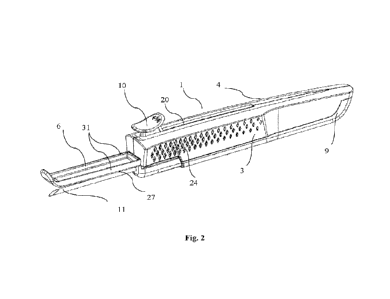
Fig. 2 is an isometric view of the applicator with the protective cover
removed. The protective
cover 5 (Fig. 1) is removed to expose the needle 11 and needle penetration
guide 6. The protective
cover 5 can be releasably engaged and disengaged with the housing. The
protective cover 5 is
configured to cover the needle 11 and the needle penetration guide 6 when the
applicator is not in
use.
The penetration guide 6 may be coupled to any portion of the applicator
housing 2 in a manner
such that it may be coupled reversibly or irreversibly in order to perform the
intended function.
The penetration guide may be molded from the same material as the housing 2 or
may be attached
as a separate element or material to the housing 2, e.g. via heat treatment,
interlock or snap fit. The
penetration guide 6 in some cases may comprise any design that may be
maintained substantially
parallel to the needle. The penetration guide 6 may have a width measured from
one side of the
penetration guide to the other side of the penetration guide. The width of the
penetration guide 6
can be narrower or wider than the needle. The penetration guide 6 may have a
length that extends
from the distal tip of the penetration guide to the proximal end of the
penetration guide that meets
or is attached to the housing 2. The length of the penetration guide 6 can be
longer, shorter or of
the same length as of the needle.
The penetration guide may comprise a plurality of substantially parallel
extensions from the
housing 2, each substantially parallel to the needle In one case, the
penetration guide is a single
extension as shown in Figs. 2-4. The penetration guide may also be designed to
allow only a single
distance between itself and the needle or it may be adjustable to allow the
practitioners to set the
distance between the two according to the depth of insertion. The gap between
penetration guide
and the needle may be between about 1 mm to about 10 mm, more preferably
between about 1.5
mm to about 5 mm, and most preferably by a distance of between about 1.5 mm to
about 3 mm.
The gap between the penetrate guide and the needle may be constant along the
length of the needle,
9
CA 03238071 2024-5- 13
WO 2023/086434
PCT/US2022/049484
or it may increase from proximally-to-distally. In some cases, the guide is a
solid and may be
transparent, translucent or opaque. In some cases, the penetration guide is
transparent. A
transparent penetration guide allows an unobstructed view of the implantation
site during implant
administration. In order to control the depth of insertion, the penetration
guide has sufficient
stiffness to prevent bending of the penetration guide during administration.
The penetration guide
can deflect not more than 1 mm on application of 1 Newton forces at the end of
their straight
portion i.e. free end of the penetration guide, preferably the penetration
guide can deflect not more
than 0.75 mm, more preferably the penetration guide can deflect not more than
0.60 mm on
application of 1 Newton forces at the end of their straight portion.
The needle penetration guide 6 is coupled to a portion of the housing and
extends distally from the
housing as shown in Fig. 4. The needle penetration guide 6 comprises an
elongate member. The
needle penetration guide can guide the needle while it is inserted under the
skin. The needle
penetration guide 6 in some cases can include a first portion comprising a
flat, plate-like element
extending distally from the housing over a majority of the length of the
needle. The plate-like
element comprises a solid, flat lower surface on a needle facing side of the
penetration guide 6,
and an opposite upper surface that may be parallel to the lower surface. The
plate-like element
may have a substantially rectangular transverse cross-section. The plate-like
element may be
transparent or translucent as described above. The first portion may further
comprise ribs 31
extending perpendicularly and/or upwardly from sides of the plate-like
element. These ribs 31
may provide further rigidity to the penetration guide 6. The ribs 31 may
extend along the left and
right edges of the flat, plate-like element of the first portion as shown in
Figs. 2 and 4. In other
cases, the rib can be located on a central portion (not on the edges) of the
flat (not shown), plate-
like element of the first portion. The first portion can be connected to the
housing and extend
distally from the housing and substantially parallel to the needle. In some
cases, a proximal wall
extending perpendicularly and/or upwardly from a proximal side of the plate-
like element may be
attached to the housing.
The first portion of the penetration guide can have a height measured from a
first needle facing
side of the penetration guide to an opposite second side. The height of the
first portion of the
penetration guide may remain constant for all or a majority of the length of
the first portion or the
penetration guide.
CA 03238071 2024-5- 13
WO 2023/086434
PCT/US2022/049484
The needle penetration guide 6 can include a second portion positioned distal
to the first portion.
The second portion can include a solid curved surface curved away from the
needle. The solid
curved surface of the second portion may comprise an extension of the plate-
like element of the
first portion. The solid curved surface of the second portion may terminate in
a rounded distal tip.
The second portion of the needle penetration guide 6 may extend to or distally
beyond the needle
11.
The shape of the distal end of the penetration guide or second portion of the
penetration guide may
be configured to prevent extremely steep needle angles relative to the skin
from being initiated for
initial needle insertion. Further, the planned implant site may be fully
visible through the
transparent penetration guide, if utilized, throughout needle advancement and
administration
procedure. The distal end of penetration guide may also provide an indication
as to where the
initial needle insertion will be initiated as well as providing a perspective
as to where the implant
will be deployed. For assisting the user in maintaining tissue depth of the
implant during the
administration procedure, the ventral or lower side of a transparent
penetration guide provides a
guide for maintaining needle advancement depth in addition to being able to
easily observe the
administration procedure throughout the needle advancement.
Fig. 3 and Fig. 4 are views of an applicator from top and left side
respectively.
Fig. 5 is an exploded isometric view of the applicator. The applicator has a
housing 2 which is
made up of three different components namely left side housing 3, right side
housing 4, and bottom
housing 9. Needle subassembly 7 is made of needle 11, needle holder 12, needle
guiding means
front 13, needle guiding means rear 16, needle assembly pins 19 (Fig 6), and
an actuator 10
attached to the needle holder 12 via flexible strap 15. The needle 11 is fixed
to a needle holder 12,
which is slidably received inside the housing 2 via housing guides front 14
and the housing guides
rear 17. The needle 11 is a hollow rod-like instrument to deliver the implant
under the skin of a
human or animal. The implant is present in the hollow interior of the needle
11. The needle guiding
means front 13 and needle guiding means rear 16 and the housing guides front
14 and the housing
guides rear 17 engage respectively to keep needle holder in place during
needle insertion while
allowing needle holder 12 to slide inside the housing when actuated by
actuator 10, i.e. retracted.
The housing guides front 14 and housing guides rear 17 are also present on
left housing 3 thereby
securing needle holder in its place firmly (not shown). The housing guides may
be a rib like
11
CA 03238071 2024-5- 13
WO 2023/086434
PCT/US2022/049484
structure. The pushrod 8 is assembled with the bottom housing 9. The pushrod 8
may be fitted with
the bottom housing 9 via molding or snap fit technique. Pushrod 8 may have
snap fit finger 18,
which is described further in detail below. The pushrod 8 includes a blunt end
29 for engaging the
implant. As shown in Fig. 8 the diameter of the pushrod 8 is tapered 30
immediately after blunt
surface as in order to facilitate needle locking after needle assembly 7 is
retracted.
Fig. 6 and Fig. 7 are cross sectional side views of the applicator when the
needle is in extended
position and retracted positions, respectively. The actuator 10 has flange 21
(Fig. 5 and Fig. 8)
which interacts with the detent ribs 22 on the left housing 3 (not shown) and
right housing 4 (Fig.
7) to prevent the needle from retracting while the needle is inserted during
the administration
procedure. The flange 21 and detent ribs 22 have complimentary surfaces to
each other. When a
user pushes down on the actuator 10, the flange 21 slides along the detent
ribs 22 and falls below
the detent ribs 22 thereby unlocking the actuator. When the actuator 10 is
further pulled back it
slides longitudinally along the track 20 (Fig. 1 and Fig. 2) that is formed by
left housing 3 and
right housing 4 and the needle assembly 7 gets retracted. The housing rib 23
formed in the left
housing 3 (not shown) and right housing 4 guide the actuator 10 and restrict
further downward
movement of the actuator 10 during the retraction procedure. At the end of
travel of the actuator
10, needle assembly pins 19 flexes past the back of the pushrod snap finger 18
and locks the needle
assembly 7 in place. The arrangement may be made to provide an audible click
at the end of travel
signaling the user that the implant has been deployed. Further, at the end of
travel of the actuator
10, the needle guiding means front 13 disengages from the housing guide front
14. After this
disengagement due to the tapered 30 region of a pushrod, the needle assembly 7
is able to move
down with respect to the pushrod and when the actuator 10 is pushed forward,
it will meet
resistance from the front of the needle guiding means front 13 misalignment
due to disengagement
with housing guide front 14 and the bevel of the needle 11 interfering with
the inner wall of the
housing just below the needle outlet aperture 25 as shown in Fig. 8. These
features provide a
means to insure that the needle is fully retracted and made safe within the
housing after the
administration procedure to prevent accidental needle sticks injury to users.
The needle can receive the implant and deliver the implant under the skin. The
needle can have a
first extended position where the needle extends distally from the housing and
a second retracted
position where the needle is retracted into the housing. The needle can allow
the implant to remain
12
CA 03238071 2024-5- 13
WO 2023/086434
PCT/US2022/049484
under the skin when the needle moves from the first extended position to the
second retracted
position.
Fig. 9 is a side cross-sectional view of the needle. In some cases, the needle
11 includes one or
more inwardly deformed crimps as an implant retaining mechanism. A deformed
crimp portion 27
of the needle 11 applies continuous pressure on the implant against the inner
wall of the needle
retaining the implant in the needle. The deformed crimps 27 may be in the form
of a bubble, a
dome, a slit, a dimple or the like. The continuous pressure provides a force
which is sufficient to
secure an implant in the needle while transporting and handling before the
insertion. The deformed
crimps provide a force or resistance to hold to an implant in order to prevent
the implant from
falling out of the needle, even if the applicator is rotated 90 degrees so the
needle tip is facing
downwards, until the needle is retracted while allowing an implant to slide
within the needle 11
without causing damage to an implant when the needle 11 is being retracted
over the implant by
actuation of the actuator 10. During retraction of the needle assembly 7 (Fig.
6 and Fig. 7) the blunt
end 29 of the pushrod 8 prevents the implant 28 (Fig. 8) from being retracted;
ultimately deploying
the implant to its position under the skin. Multiple deformed crimps can be
used to provide further
assurance that implants will be retained regardless of implant orientation
inside the needle. The
implant retaining mechanism is located at any position on the needle 11 to
serve the desire purpose_
In some cases, a needle 11 includes one dimple as an implant retaining
mechanism, for example,
on the dorsal side of the needle. In some cases, a needle 11 includes two
dimples 27 as an implant
retaining mechanism. The two dimples 27 are located at different positions on
the needle 11, for
example, on the dorsal and ventral sides of the needle and, for example, the
proximal dimple being
on dorsal side. In an example, two dimples 27 can be spaced 180 degrees apart
radially. In some
examples, two dimples 27 can be spaced 180 degrees apart radially and 2 mm to
10 mm apart
axially, preferably 4 mm apart axially as shown in exploded view A of Fig. 9.
In another case, a
needle 11 includes three dimples as an implant retaining mechanism. In some
cases, three dimples
coplanarly spaced 120 degrees apart on the needle circumference. A depth of
deformed crimp
portion 27 is in the range from about 0.01mm to about 0.2mm, more preferably
from about
0.025mm to about 0.15mm, more preferably about 0.025 to about 0.1mm. Each
deformed crimp
portion 27 may have different depth irrespective of the number of deformed
crimp portion 27 on
the needle 11.
13
CA 03238071 2024-5- 13
WO 2023/086434
PCT/US2022/049484
In order to facilitate the implant insertion in the needle 11, a large slot 26
is provided in the needle.
The slot 26 is either molded or cutout. In some cases, a slot 26 is a 180
degree cutout with a length
which is more than the length of the implant. In some cases, a slot is of
about lOmm to about
60mm in length, more preferably a slot is of about 15mm to about 45 mm in
length. In some cases,
the slot is provided in between two ends of the needle (between a proximal end
and a distal end of
the needle). In some cases, the slot is present at the proximal portion of the
needle which is opposite
to the sharp end or bevel i.e. distal end, and on the ventral side of the
needle as can be seen in Fig.
9. For example, the slot is positioned in a sidewall of the needle between a
proximal end and a
distal end of the needle and the implant can be loaded into the applicator
through the slot provided
in the sidewall of the needle between two ends of the needle.
Fig. 10 shows a perspective view of an applicator receiving an implant. Before
insertion of the
implant the applicator is either a kit or preassembled applicator. When in the
form of a kit, a bottom
housing 9 remains a separate component and is not assembled to the applicator
leaving access to
the slot 26 on the needle assembly 7. When the applicator is preassembled it
is present as a single
piece. The bottom housing 9 is separated from the preassembled applicator to
give access to the
slot 26 on the needle assembly 7 just before the insertion of the implant 28.
The applicator
assembly is then oriented upside-down and the implant 28 is dropped into the
slot 26 of the needle
11. Fig. 11 is a cross section view of an applicator showing an implant
immediately after it is
placed in the needle 11 through the large slot 26. Bottom housing 9 is then
slid into side housings
3 and 4 with pushrod 8 incorporated into the bottom housing 9 pushing the
implant 28 into correct,
pre-deployment position and the housing is fully closed. When fully assembled
the pushrod 8 is
partially located inside the needle 11. The loading of an implant can be
advantageous as an implant
is directly introduced into the needle to prevent the damage of a delicate
implant which otherwise
may cause damage if it is placed directly in the end of the applicator housing
or needle holder
assembly and then pushed into the needle. The implant 28 is directly dropped
lengthwise at an
angle perpendicular to the longitudinal axis of the needle 11 into the slot 26
of the needle 11
thereby avoiding the consequential damage.
In an example, an applicator is especially suitable for use with implants that
slowly release an
active substance over an extended period of time. An implant of this type,
which can release a
contraceptive agent or hormone replacement agent in virtually constant
quantities over a period of
14
CA 03238071 2024-5- 13
WO 2023/086434
PCT/US2022/049484
at least 2 years, and, in some cases, for about 3 to 5 years. An example of
such an implant is a
single-rod contraceptive implant that provides protection against pregnancy
for an extended period
of time, for example 3 years. The implant is cylindrical or virtually
cylindrical with a diameter
about 1 mm to about 3 mm, and, in some cases, about 2 mm, and possesses a
variable length. The
length may be between 10 mm and 50 mm. The contraceptive active substance,
which can be
employed in the implant is a therapeutically effective amount of highly active
progestagen,
particularly 3-keto-desogestrel medroxyprogesterone, levonorgestrel or
gestodene. 3-keto-
desogestrel also known as etonogestrel. These contraceptive substances are
highly active
substances which show already an effective progestational action with a daily
dosage of about 15-
100 Mg. In one case, an implant comprises of a non-biodegradable rod measuring
nominally 40
mm in length and 2 mm in diameter and 3-keto-desogestrel. After insertion, the
rod slowly releases
3-keto-desogestrel for a period of 2 to 5 years. The implant may contain a
radio-opaque element
such as barium sulphate, titanium oxide, bismuth oxide, tantalum, tungsten, or
platinum. The radio-
opaque agent facilitates viewing of the implant during insertion and at any
point while the device
is implanted.
The hormone replacement agents that can be employed in the implant include an
estrogen and
progesterone components. Estrogen therapies are numerous, and include those
indigenous to the
human ovary, for example, estradiol, estriol, conjugated equine estrogen
(CEE). Progesterone
component includes either a synthetic version of the hormone progesterone
(such as
dydrogesterone, medroxyprogesterone, norethisterone and levonorgestrel), or a
version called
micronised progesterone (sometimes called body identical, or natural) that is
chemically identical
to the human hormone.
When in use, a medical professional can take the applicator 1 in one hand,
e.g. with the thumb on
one side of the housing and the fingers on the other side, and insert the
needle 11 under the skin of
a patient. The applicator 1 may be held on the left and right side housing 3
and 4 portions of the
housing proximal to the needle penetration guide 6. During insertion,
transparent penetration guide
6 enables clear view for the medical professional of the needle 11, the
planned implant site, and
advancement and administration procedure. Subsequently, after insertion, the
actuator 10 is
unlocked and is pulled rearwards, for example with the index finger of the
hand that holds the
applicator, and the needle 11 is retracted from the skin of the patient.
CA 03238071 2024-5- 13
WO 2023/086434
PCT/US2022/049484
The figures illustrates aspects of the present disclosure, and is set forth to
assist in understanding
the present disclosure. This example should not be construed as specifically
limiting the present
disclosure described and claimed herein. Variations of the present
disclosures, including the
substitution of all equivalents now known or later developed, which would be
within the purview
of those skilled in the art, and changes in formulation or minor changes in
experimental design,
are considered to fall within the scope of the present disclosure and appended
claims.
Groupings of alternative elements or embodiments disclosed herein are not to
be construed as
limitations. Each group member may be referred to and claimed individually or
in any combination
with other members of the group or other elements found herein. It is
anticipated that one or more
members of a group may be included in, or deleted from, a group for reasons of
convenience and/or
patentability.
The embodiments and examples disclosed herein are illustrative of the
principles of the disclosure.
Other modifications that may be employed are within the scope of the present
disclosure. Thus, by
way of example, but not of limitation, alternative configurations may be
utilized in accordance
with the teachings herein. Accordingly, the present disclosure is not limited
to that precisely as
shown and described.
16
CA 03238071 2024-5- 13