Note: Descriptions are shown in the official language in which they were submitted.
WO 2023/138831
PCT/EP2022/084867
1
SCREENING APPARATUS
The present invention relates to material handling equipment, in particular to
screening
apparatus for use in waste material handling, for example for use in the
recycling industry.
Background to the Invention
Within the material handling industry there is a need for the ability to
remove valuable
material, for example stones, from other inert landfill material such as soil
and muck.
Material collected from the demolition of buildings, excavations or by
reclamation of rocky
soil exhibits heterogeneous dimensions, typically contains debris of value
combined with
rubble, sand and other objects of small dimensions. There are a number of
conventional
mechanical screening methods used to separate these materials into multiple
grades by
particle size.
At the high throughput expensive end are washing plants. Washing plants
process
construction and civil engineering wastes into clean homogenous recycled
product by
washing the material to remove contaminants and extract silt and clay which
bind the
constituents together. The throughput can be very high, up to about 120 tonnes
per hour.
However, washing plants are very expensive to purchase, hire and operate. As
well as
being high cost, the whole process uses a lot of energy and water.
Furthermore, the
waste/dirty water is a big issue and has to be settled in settle ponds, often
with the addition
of chemicals to speed up the settling process.
On the cheaper, less efficient, side screening buckets may be used to separate
material. A
screening bucket must be attached to an excavating machine. The bucket
typically has
rotatable drums which effect screening, crushing or mixing of a material
present in the
bucket and at the same time deliver a screened, crushed or mixed material out
of the bucket
between or through the drums. Disadvantages with such buckets include the fact
that the
throughput is very low, usually about 20 tonnes per hour and the process is
laborious for
the driver of the excavator who has to frequently slew around between the
different piles of
material, for example between piles of stones and piles of fines material.
CA 03239064 2024- 5- 23
WO 2023/138831
PCT/EP2022/084867
2
It is therefore an object of the present invention to provide a screen for
inert landfill material
which alleviates the above disadvantages and/or provides a suitable
alternative.
Summary of the Invention
The present invention relates to apparatus for use in screening and conveying
waste
material, which allows oversize material to self-discharge and which avoids
build-up of
waste material on the apparatus.
Accordingly, a first aspect of the present invention is a screen for accepting
waste material,
the waste material comprising fines and oversize material, wherein the screen
comprises:
a trough with a top opening, a base opening for discharging the fines material
and
an oversize material outlet for discharging the oversize material;
driven elongate rotating members for causing movement of the waste material,
wherein each rotating member comprises a shaft and a plurality of mutually
parallel blades,
wherein each blade independently has a plurality of radial protrusions which
act on the
material during the movement thereof, wherein for one or more blades on each
shaft
independently, at least one of the radial protrusions on the or each blade is
an extended
radial protrusion,
wherein the material to be screened is introduced at one end of the shafts and
expelled at the other end,
characterised in that each elongate rotating member independently is held and
rotatably mounted at both ends,
wherein the driven elongate rotating members comprise a first plurality of
driven
elongate rotating members disposed in a first arc along one side and along at
least a portion
of the base of the trough for causing circular or helical flow of the waste
material and a
second plurality of driven elongate rotating members disposed in a second arc
along the
other side of the trough and along at least a portion of the base of the
trough for causing
circular or helical flow of the waste material,
wherein, for each plurality of driven elongate rotating members, at least one
elongate rotating member runs at a different speed to the other elongate
rotating members,
and wherein the speed of the elongate rotating members does not decrease
towards the
top opening of the trough.
CA 03239064 2024- 5- 23
WO 2023/138831
PCT/EP2022/084867
3
By extended radial protrusion is meant a radial protrusion on a particular
blade that is longer
than the other radial protrusions on that blade.
The driven elongate rotating members together form a screening surface,
wherein fines
material falls between the rotating members and oversize material does not.
The elongate rotating members cause circular or helical flow of the waste
material above
the screening surface. The material is introduced at one end of the shafts and
expelled at
the other end. The curved placement of the elongate rotating members results
in the waste
material being flipped and tossed which increases the screening efficiency and
causes any
sticky material to break up. The speed of the rotating members does not
decrease in the
direction of material flow, i.e., towards the top of each arc.
During rotation of the shafts of the elongate rotating members, each extended
radial
protrusion on a particular shaft comes closer to the shafts on either side of
that shaft,
clearing any debris from the adjacent shafts and any debris stuck between the
blades of the
adjacent shafts.
Due to the fact that not all of the elongate rotating members run at the same
speed, the
extended radial protrusions do not always hit an adjacent shaft at the same
point every
revolution, only clearing one particular area of the shaft. Instead, the or
each extended
radial protrusion of the rotating member running at a different speed hits an
adjacent shaft
at a different location every revolution, cleaning right around the adjacent
shaft.
The rotating members do not slow down in the direction of material flow. If
they were to get
slower in the direction of material flow, the material would back up, and
would be pulled
down by the faster rotating member.
In a preferred embodiment, the rotating members are interconnected.
Alternatively, the
rotating members are each independently driven.
There are preferably at least three elongate rotating members per plurality,
particularly
preferably from about 4 to about 12, e.g., 5 or 6.
In a preferred embodiment, the rotating members rotate in the range of from
about 90 to
about 200 rpm. However, this is not considered to be limiting and other speeds
are
CA 03239064 2024- 5- 23
WO 2023/138831
PCT/EP2022/084867
4
considered to be within the scope of the invention. Particularly preferably,
the rotating
members rotate at variable speed.
The rotating members are preferably actuated by a motor and mechanical
transmission.
The motor may be hydraulic or electric, for example a variable speed electric
motor. In the
embodiment wherein the rotating members are interconnected, a first toothed
pulley is
typically keyed onto the output shaft of the motor and a plurality of second
toothed pulleys
are keyed onto respective ends of the rotating members and coupled to the
first toothed
pulley by means of chains.
The speeds of the rotating members on one side of the trough are preferably a
mirror of the
speeds on the opposite side, i.e., opposing shafts run at identical speeds.
In a particularly preferred embodiment, the first plurality of rotating
members run in the
opposite direction to the second plurality of rotating members. For example,
if the shafts of
the first plurality of driven elongate rotating members operate in the
clockwise direction,
shafts of the second plurality of driven elongate rotating members operate in
the anti-
clockwise direction and vice versa.
Preferably, each elongate rotating member independently is adjacent at least
one shaft on
either or both sides running at a different speed, particularly preferably by
use of different
size sprockets.
Preferably, the radial protrusions are curved radial protrusions. For example,
the blades
may be polyurethane stars such as curved, hexagonal, circular, or straight
legged stars.
However, this is not to be considered limiting and other materials and shapes
are
encompassed within the scope of the invention, provided each blade has at
least one radial
protrusion longer than the others on that blade.
In a further aspect the invention provides a screening apparatus comprising a
frame, a feed
conveyor mounted at one end of the frame and a screen as described
hereinabove.
Preferably, the screen is mounted on the frame about a pivot axis and is
pivotable about
the pivot axis such that the inlet end and/or discharge end of the screen may
be raised or
lowered. In these embodiments, the elongate rotating members are each
independently
CA 03239064 2024- 5- 23
WO 2023/138831
PCT/EP2022/084867
perpendicular to the pivot axis. However, this is not to be considered
limiting and the screen
may instead be mounted to the frame at a predetermined fixed angle such that
the oversize
material outlet is lower than the inlet end of the screen, preferably wherein
the
predetermined fixed angle is in the range of from about 2 degrees to about 15
degrees,
5 particularly preferably in the range of from about 5 degrees to about 10
degrees, e.g., 7
degrees.
In a preferred embodiment, the pivot axis is at the outlet end of the screen.
However, this
is not to be considered limiting and the pivot axis may alternatively be
located at the inlet
end or anywhere between the inlet and outlet ends of the screen.
In a preferred embodiment, the screen is mounted on the frame such that at
least a portion
of the top opening of the trough is located beneath the feed conveyor.
Alternatively, or
additionally, the screening apparatus further comprises a static feed plate
between the feed
conveyor and the screen such that the waste material to be screened falls from
the feed
conveyor onto the static feed plate, bounces or slides off the plate and then
drops into the
screen.
The screening apparatus according to the invention is preferably static for
placement above
containment bays for collecting the discharged fines and oversize material.
Such
containment bays may be made of shuttered concrete, or manufactured from
steel, concrete
blocks and the like. However, rather than being static, the screening
apparatus may be
provided with any one or more of wheels, tracks and hooklift.
The oversize material outlet is preferably at the front of the trough, i.e.,
at the opposite end
of the screen to incoming water material.
In a preferred embodiment, the screen further comprises a feed inlet for
accepting the waste
material from the feed conveyor such that the feed inlet is beneath the feed
conveyor,
particularly preferably wherein the feed inlet is in the form of a chute,
e.g., a three-sided
chute. In this embodiment, the outlet is preferably at the opposite end of the
trough to the
inlet.
The screen is preferably pivotally mounted to the frame such that the angle
may be altered
to dictate retention time of the waste material within the trough. For
example, the screen
CA 03239064 2024- 5- 23
WO 2023/138831
PCT/EP2022/084867
6
may be mounted at 0 degrees with respect to the frame. Alternatively, for
transport, the
screen may be pivoted along the pivot axis such that the screen is angled and
mounted with
the inlet end lower than the outlet end in order to retain the material, e.g.,
with the outlet
end upwards up to about 2.5 degrees.
Alternatively, the screen may be pivoted along the pivot axis such that the
screen is angled
and mounted with the inlet end higher than the outlet end, e.g., the outlet
lowered up to
about 15 degrees, such that the material remains on the screen for a shorter
time. In this
embodiment, the larger the angle, the less time the material is on the screen.
In a preferred embodiment, the screening apparatus further comprises a ram
assembly to
alter the pivot angle of the screen with respect to the frame. The ram
assembly may be
directly attached to the screen or may be located elsewhere on the screening
apparatus.
Alternatively, the screen could be lifted, e.g., using a crane, and pinned in
position.
In a preferred embodiment, the screening apparatus further comprises one or
more
conveyors to collect and stockpile screened material.
Additionally, or alternatively, the screening apparatus preferably comprises a
plurality of
screens in series, particularly preferably two screens in series. The
plurality of screens may
be in line or stepped with respect to each other. In these embodiments only
the first screen
may be provided with a feed inlet. Both embodiments enable an increase in the
screening
length.
In addition to enabling increased screen length, the screens in series may
also be used to
give additional product sizes, i.e., the first screen allowing fines material
of a diameter up to
about 10 mm through its base opening, the second allowing fines material of a
diameter up
to about 25 mm through its base opening and the remaining material exiting the
machine
through the oversize material outlet.
In order to enable the screen to be removed from the screening apparatus for
ease of
maintenance of the screen, the screen is preferably removably mounted to the
frame. For
example, the screen preferably slides with respect to the frame for removal.
The feed
conveyor is preferably also slidably mounted to the frame such that it can be
moved out of
the way to facilitate removal of the screen.
CA 03239064 2024- 5- 23
WO 2023/138831
PCT/EP2022/084867
7
Brief Description of the drawings
Certain preferred embodiments of the present invention will now be described,
by way of
example only, with reference to the accompanying drawings in which:
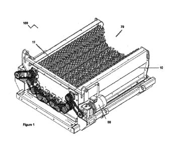
Figure 1 shows a perspective view of the screen according to the invention;
Figure 2a shows a plan view of the screen of Figure 1;
Figure 2b shows a sectional view along line A-A in Figure 1;
Figure 2c shows a sectional view along line B-B in Figure 1;
Figure 3 shows an end view of the screen of Figure 1;
Figure 4 shows a rear perspective view of the screen of Figure 1;
Figure 5 shows an outlet end view of the screen of Figure 1;
Figure 6 shows a preferred blade with extended radial protrusion for use on
the elongate
rotating members of the screen of Figure 1; and
Figure 7 shows a perspective view of a preferred screening apparatus according
to the
invention.
Detailed Description
Various embodiments of the present invention will be described in detail with
reference to
the drawings, where like reference numeral represent like parts and assemblies
throughout
the several views.
Referring to the drawings, Figures 1 to 5 show a preferred screen according to
the invention,
generally referred to herein by reference numeral 100, for accepting waste
material, the
waste material comprising fines and oversize material.
CA 03239064 2024- 5- 23
WO 2023/138831
PCT/EP2022/084867
8
Screen 100 comprises a trough 10 with feed inlet 11 and base opening (not
shown) and a
plurality of driven elongate rotating members 21, 22, 23, 24, 25, 31, 32, 33,
34, 35 for
causing movement of waste material. Arrows F in Figure 4 show the direction of
flow of the
material within screen 100 during use.
Inlet 11 is for accepting waste material, e.g., from a hopper. Base opening
(not shown) is
for discharging fines material.
Five interconnected driven elongate rotating members 21, 22, 23, 24, 25 are
disposed in a
first arc 20 along one side and along at least a portion of the base of trough
10 for causing
circular or helical flow of waste material within trough 10 above the
screening surface
formed by arc 20 such that the speed of the elongate rotating members does not
decrease
in the direction of material flow. In the preferred embodiment shown, the
speed rotating
member 21 runs at is faster than the speed rotating member 22 runs at, the
speed rotating
member 22 runs at is faster than the speed rotating members 23 and 24 run at
and the
speed rotating members 23 and 24 run at is faster than the speed rotating
member 25 runs
at.
Another five interconnected driven elongate rotating members 31, 32, 33, 34,
35 are
disposed in an opposing second arc 30 along the other side of trough 10 for
causing a
second, opposing circular or helical flow of waste material within trough 10
above the
screening surface formed by arc 30. The speeds rotating members 31, 32, 33,
34, 35 run
at mirror those of rotating members 21, 22, 23, 24, 25, i.e., rotating members
21 and 31 run
at identical speeds and so on. In the embodiment shown, the different speeds
are achieved
by using different size sprockets.
Rotating members 21, 22, 23, 24, 25 run in the opposite direction to rotating
members 31,
32, 33, 34, 35. For example, if the shafts of interconnected driven elongate
rotating
members 21, 22, 23, 24, 25 operate in the clockwise direction, shafts of
interconnected
driven elongate rotating members 31, 32, 33, 34, 35 operate in the anti-
clockwise direction
and vice versa.
Each rotating member 21, 22, 23, 24, 25, 31, 32, 33, 34, 35 comprises a shaft
40 and a
plurality of mutually parallel blades 50, wherein each blade independently has
a plurality of
curved radial protrusions 51 which act on the material during the movement
thereof, wherein
CA 03239064 2024- 5- 23
WO 2023/138831
PCT/EP2022/084867
9
one of the radial protrusions on each blade 50, extended radial protrusion 52,
is longer than
the other radial protrusions 51 on that blade. This is more clearly shown in
Figure 6.
As is clear from Figure 3, first toothed pulley 41 is keyed onto output shaft
61 of variable
speed electric motor 60 and a plurality of second toothed pulleys 42 are keyed
onto
respective ends of rotating members 21, 22, 23, 24, 25 outside of trough 10
and coupled to
first toothed pulley 41 by means of chains 43.
The number of teeth on the ends of rotating members 21, 22, 23, 24, 25
increases in the
direction of material flow, with rotating member 21 having 15 teeth, rotating
member 22
having 16 teeth, pulleys 44 and 45 having 17 teeth and pulley 46 having 18
teeth.
For each blade 50, during rotation of shafts 40, extended radial protrusion 52
comes closer
to shafts on either side than radial protrusions 51 on that blade, thus
clearing debris from
adjacent shafts and stuck between the blades. Due to the fact that not all
rotating members
run at the same speed, extended radial protrusion 52 does not always hit an
adjacent shaft
at the same point every revolution, only clearing one particular area of the
shaft. Instead,
each extended radial protrusion 52 of the rotating member running at a
different speed hits
an adjacent shaft 40 at a different location every revolution, cleaning right
around the
adjacent shaft.
Screen 100 further comprises oversize material outlet 70 for discharging
oversize material.
In the preferred embodiment illustrated in Figure 6, blades 30 are curved
polyurethane
stars. However, this is not to be considered limiting and other materials and
shapes are
encompassed within the scope of the invention, provided each blade has at
least one radial
protrusion longer than the others on that blade.
Figure 7 shows a preferred screening apparatus according to the invention,
generally
referred to herein by reference numeral 1. As shown, screening apparatus 1
comprises
frame 110, feed hopper 120 mounted at one end of frame 110 and screen 100
angled and
mounted on frame 110 such that feed inlet 11 is located beneath the output end
of feed
hopper 120 and feed inlet 111 is higher than outlet 70.
CA 03239064 2024- 5- 23
WO 2023/138831
PCT/EP2022/084867
In the preferred embodiment shown in Figure 7, screening apparatus 1 further
comprises
tracks 130. Additionally, screening apparatus 1 further comprises conveyor 140
to collect
and stockpile screened fines material and conveyor 150 to collect and
stockpile screened
oversize material.
5 It is to be understood that the invention is not limited to the
specific details described herein
which are given by way of example only and that various modifications and
alterations are
possible without departing from the scope of the invention as defined in the
appended
claims.
CA 03239064 2024- 5- 23