Note: Descriptions are shown in the official language in which they were submitted.
WO 2023/115098
PCT/AU2022/051391
Energy Storage
Cross references to related applications
The present patent application claims the benefit of the earlier filing date
of
Australian provisional patent application 2021904176, filed on 21 December
2021,
the entirety of each such application is hereby incorporated by reference
herein
as if fully set forth herein.
Field of the invention
The present invention relates to a device for the capture, storage and release
of thermal energy as well as a method of capturing, storing and release of
energy.
Background to the invention
Renewable energy sources such as wind and solar power are becoming
increasingly important environmentally and economically. According to the WMO
(World Meteorological Organization), the concentration of greenhouse gases in
the
atmosphere reached 400ppm in 2015 and passed 413ppm by 2020. A speedy
transition is required to stabilise the concentration of greenhouse gases at a
generally
acknowledged critical threshold of 450ppm. Delays in the implementation of
renewable
and carbon neutral energy sources narrow the window for action and also
increase
the cost of transforming the energy sector by an estimated $500 billion per
year.
Unfortunately, most forms of renewable energy (with the exception of
geothermal and hydroelectricity) suffer from intermittency of supply. For
example, the
diurnal cycle and weather conditions directly affect solar generation. Wind
and wave
sources are also intermittent and the energy depends on the prevailing
environmental
conditions.
In order to make renewable energy sources more attractive and to increase
the availability of the electric energy generated from such sources, energy
needs to
be stored during times of surplus and released during times where demand would
otherwise exceed supply.
1
CA 03239132 2024- 5- 24
WO 2023/115098
PCT/AU2022/051391
Conventional energy storage technologies exist based upon well established
chemical, electrochemical or mechanical means. Batteries are well known, for
example, and the pumping of water up to reservoirs for subsequent
hydroelectric
generation is also a well established technical field. Unfortunately, many of
these
technologies have relatively low energy storage densities (low stored energy
per unit
volume) and the energy storage by chemical, electrochemical or mechanical
means
are all subject to energy losses in the storage-recovery cycle additional to
those
associated with eventual energy utilisation.
For thermal sources of energy, direct Thermal Energy Storage (TES) can be
made extremely efficient, suffering only environmental losses through the
insulation
envelope. For example, sensible heat based concentrated solar thermal (CST)
plants,
which use thousands of tonnes of molten KNO3/NaNO3 salt for sensible heat
storage,
have a relatively high return thermal efficiency.
Recently, energy storage devices have been proposed which use solid
storage materials in the form of stones or concrete, in order to store thermal
energy.
The stored thermal energy can be used in times of high demand to generate
steam
for heating or for driving a steam power plant, in order to convert the stored
thermal
energy back to electric energy.
One such form of solid energy storage material is that disclosed in (WO
2014/063191 Al) which utilises miscibility gap alloys as thermal storage
materials.
These materials comprise a containment matrix within which are dispersed
microparticles of a meltable material. At low temperatures, below the melting
point of
the meltable material, the whole is solid. At temperatures above the melting
point of
the alloy from which the microparticles are made, the microparticles are
liquid. The
material is highly efficient in terms of energy storage and release which take
place via
thermal transfer with the surface of the matrix.
The term "microparticles" can be used in an absolute or relative sense. For
instance, in the absolute sense, microparticles can refer to particles which
are of a
size less than 100 m in size, for example 10 m or even 1pm or smaller.
2
CA 03239132 2024- 5- 24
WO 2023/115098
PCT/AU2022/051391
Alternatively, in the relative sense, microparticles can refer to particles
which
are at least two orders of magnitude (>100x) or more smaller than the overall
storage
block dimension into which the thermal storage material is formed.
This form of thermal storage is direct as sensible heat due to temperature
rise
or latent heat due to a phase change. Such phase change systems are
potentially very
useful as they exhibit very high energy storage density, much higher than
competing
technologies. Moreover, the phase change system can easily be tailored to the
target
application by altering its constituent materials to those with melting points
in the
desired temperature range, thus modifying its thermal storage and release
characteristics.
In addition to a high energy density per unit volume, such materials also have
a relatively short time requirement to recharge and discharge. and are
relatively cost
effective.
The application of efficient thermal energy storage systems to capture heat
from renewable sources like solar or waste heat from existing industries can
offer
significant savings and reduction in the emission of greenhouse gases.
Approximately 50% of energy used for heating is consumed by residential
space heating applications with the remainder being utilized by industry for
low-
temperature steam generation and process drying.
Further, if effective thermal storage solutions are developed, the range of
applications is not limited to renewable energy sources. The technology can
also be
used for load shifting applications in conventional technologies, for example,
through
the conversion of fossil fuel power stations into storage and dispatch
systems.
Alternatively, thermal storage solutions can be implemented for recovering
wasted
energy from large-scale industrial processes and redispatching it during plant
start-up.
Any discussion of the prior art throughout the specification should in no way
be considered as an admission that such prior art is widely known or forms
part of
common general knowledge in the field.
3
CA 03239132 2024- 5- 24
WO 2023/115098
PCT/AU2022/051391
It is an object of the present invention to overcome or ameliorate at least
one
of the disadvantages of the prior art, or to provide a useful alternative,
preferably new
materials that are suitable for use as high energy density high thermal
conductivity
thermal storage materials.
Summary of the invention
In a first aspect of the present invention, there is provided an energy
storage
device comprising:
at least one heating device;
a thermal storage body comprising at least one thermal storage block formed
from a miscibility gap alloy, wherein said at least one thermal storage block
is
arranged such that at least one heat transfer channel adapted to receive heat
transfer fluid flow and/or said at least one heating device is formed therein;
thermal insulation unit surrounding said thermal storage unit such that said
thermal storage unit is substantially thermally insulated; and
at least one substantially impermeable shell surrounding the thermal storage
body and/or the thermal insulation such that the heat transfer fluid is
substantially contained,
wherein heat can be charged or discharged from said thermal storage body by
thermal
transfer between said at least one heat transfer channel and at least one
thermal
storage block.
Structure of Device
In some embodiments, the energy storage apparatus is a thermal energy
storage apparatus. The apparatus of the present invention is configured to
store
thermal energy to overcome or ameliorate the disadvantages of known thermal
energy
storage solutions, including but not limited to those that utilise
recirculating molten
salts, conductive solid materials such as graphite and material with high dead-
space
volume such as granular material. These include long term degradation of the
storage
and discharge capacities through destructive expansion, crumbling or erosion
of the
4
CA 03239132 2024- 5- 24
WO 2023/115098
PCT/AU2022/051391
solid storage material itself or vessels carrying the fluids, the natural
discharge of the
stored thermal energy, difficulty in maintenance of thermal contact with heat
exchange
infrastructure and its high set-up expense. Thermal energy storage utilising
miscibility
gap alloys by comparison have a higher energy density than sensible heat-only
solutions due to the fact that it is also stores latent heat energy, while
also displaying
little hysteresis or long-term degradation in structural rigidity/performance
upon
repeated charging, storage and discharge of thermal energy.
In some embodiments of the present invention, the thermal storage body
comprises one or more thermal storage blocks arranged to form at least one
heat
transfer channel inside of the thermal storage body. The heat transfer
channels
provide an exposed surface acting as an interface for transferring thermal
energy
between the heat transfer fluid or a heating device and the storage body by
conduction, convection and/or radiation.
The person skilled in the art would appreciate that thermal transfer between a
solid thermal storage body and a heat transfer fluid can be made by contact
directly
therebetween or through a heat exchanger apparatus. Accordingly, the at least
one
thermal storage block formed from a miscibility gap alloy (herein "MGA storage
block")
can be either directly exposed to the flow of heat transfer fluids, or be in
contact with
the conductive walls of a heat exchanger apparatus. The thermal storage body
comprises a heat transfer channel having at least two openings such that
forced flow
of the heat transfer fluid therein can be facilitated by apparatuses such as
pumps
and/or blowers located outside of the energy storage device.
The MGA storage blocks can be of any shape, but will be described herein
with reference to hexahedral storage blocks. Examples of hexahedral storage
blocks
are cubes or elongate square or rectangular prisms.
Preferably the thermal storage blocks are directly exposed to the heat
transfer
fluid by directly passing said fluid through the heat transfer channel. In
this
embodiment, thermal energy is passed by conduction and convection between the
fluid and the MGA thermal storage blocks directly, without any conductive
barrier such
as a heat exchanger apparatus wall in between. The inventor found this
configuration
to be advantageous in light of the density and conductivity of the MGA
material forming
5
CA 03239132 2024- 5- 24
WO 2023/115098
PCT/AU2022/051391
the heat storage blocks negating the benefits of heat exchanger piping,
resulting in
improved heat retention in storage and transfer during charge/discharge.
The person skilled in the art would appreciate that the thermal storage body
can be, but is not necessarily required to be constructed from a single
thermal storage
block. Preferably, the thermal storage body is assembled from a plurality of
thermal
storage blocks with sufficient strength to support their own and the storage
body's
weight. While a unitary construction of the thermal storage body would allow
for
improved conduction and heat retention within the miscibility gap alloy
forming the
single thermal storage block, such a construction would pose difficulties in
forming the
heat transfer channels, and could result in inadequate heating and/or heat
extraction
during operation of the energy storage device. Benefits of constructing a
thermal
storage body from multiple thermal storage blocks include improved uniformity
in heat
charge/discharge across the internal cross section of storage body achievable
by an
increased number and ease of incorporating heating devices and heat transfer
channels for fluids.
The thermal storage blocks can be formed to fulfil a variety of criteria if
desired,
for example, such as maximising contact area with a heat transfer flow, for
modular
storage and assembly or to facilitate transportation. or be sized to retain a
predetermined amount of heat.
Preferably, the at least one thermal storage block is fabricated such that
when
fully constructed, the thermal storage body which it comprises, includes
appropriate
channels or recesses to accommodate fluid flow and heating devices. Where the
thermal storage body is constructed from multiple thermal storage blocks
formed from
a miscibility gap alloy, the blocks may simply be stackable hexahedral blocks
or in
some embodiments they may be fabricated such that they provide structural
support
for the assembled thermal storage block, In one embodiment, the thermal
storage
blocks slot into each other via pre-fabricated slots, in this regard, the heat
transfer
channels may be fabricated in the thermal storage blocks for accommodating the
heating device and/or heat transfer fluid flow or may be formed by particular
arrangements of the thermal storage blocks, the channels formed therebetween.
6
CA 03239132 2024- 5- 24
WO 2023/115098
PCT/AU2022/051391
When the thermal storage body is constructed from multiple thermal storage
blocks, the thermal storage blocks are arranged such that their dimensional
expansion
under thermal load is taken into account in its structural support and
rigidity. In this
regard, permanent deformation of the thermal storage body caused by thermal
expansion-related stresses and strains during heating and thermal storage can
be
prevented by incorporating at least one spacer between said multiple thermal
storage
blocks. Moreover, by preventing excessive straining of the thermal storage
blocks
under thermal expansion, thermal-related creep and associated issues can be
also be
alleviated, including a loss of structural strength, breakdown of the blocks
and a build-
up of internal pressure by the expansion of the blocks against each other
(also known
as thermal ratcheting).
A spacer in this regard is a solid, thermally resistant material that is
adapted
to abut against the outer surface of the each said multiple thermal storage
blocks such
that an interstitial space is created and maintained between an array thereof.
In one
example, the spacers are provided adjacent to each corner of a hexahedral MGA
block
comprising the thermal storage body such that interstitial space is provided
adjacent
to at least two sides thereof. This interstitial space provided between the
MGA blocks
can constitute the heat transfer channels for facilitating thermal transfer
between the
MGA blocks and the heating element and/or the heat transfer fluid. Preferably,
the
spacer is formed from metallic material such that is adapted to maintain
structural
rigidity under expansionary load of the MGA blocks in order to maintain said
interstitial
spaces and prevent deformation of said blocks.
The shape of the spacers in this regard are adapted based on several factors,
including the shape of the thermal storage blocks, the desired volume of the
interstitial
spaces, and thus the heat transfer channels, as well as the thermal expansion
coefficient of the material employed in the thermal storage block. In one
embodiment,
the spacer is formed of a metallic bar with a "T"-shaped cross-section,
adapted to
accommodate and abut both corners and a side of a hexahedral thermal storage
block.
In another embodiment, the spacer is an elongated cylindrical bar of differing
lengths.
In a further embodiment, both types of spacers are used in an alternating
manner to
secure MGA blocks in an array thereof, forming the thermal storage body.
7
CA 03239132 2024- 5- 24
WO 2023/115098
PCT/AU2022/051391
To avoid energy loss to the external environment, the thermal storage body is
surrounded by insulation material comprising the thermal insulation unit. The
insulation
material in the form of panels, blocks, mineral wools, foams and/or insulation
blanks
are suitably located on an outer surface of the thermal storage body to
substantially
insulate therein, and thus minimise thermal energy lost to the external
environment. A
person skilled in the art would appreciate the insulation needs for the
thermal storage
body and would be able to suitably design an insulation solution according to
the
required specifications.
Further to the above, there is also provided a substantially fluid-tight
containment or shell structure to prevent expanded heated gases and/or heat
transfer
fluids from escaping the energy storage device. In this regard, at least one
impermeable layer of material is provided on the outside of the thermal
storage body
to surround it and contain the heat transfer fluids therein. Preferably, this
containment/shell structure is formed from metals, more preferably a steel
alloy such
as mild steel or stainless steel . A further preferable embodiment can also
comprise
an inner and outer shell with the insulative material provided therebetween.
In such a
structure, the inner shell provides substantial sealing of the thermal storage
body and
heat transfer fluids, while the outer shell provides improved thermal
containment and
structural rigidity by encapsulating the insulative material.
Use of MGA
As discussed above, the at least one thermal storage block comprising the
thermal storage body is formed from a miscibility gap alloy (MGA). The term
"miscibility
gap" in the context of this alloy means that there is to some extent
immiscibility
between the components of the alloy, and at certain ratios and temperatures
the alloy
de-mixes from a miscible alloy to form distinct phases that co-exist in the
microstructure of the thermal storage block. An alloy in this regard refers to
a material
comprising a thermodynamically stable mixture of at least two constituent
materials
selected from metallic, semi-metallic or non-metallic materials.
As discussed in PCT/AU2013/001227, it is known that high temperature
thermal storage is efficiently achieved in a compact footprint using
thermodynamically
stable two phase mixtures in which the active phase that undergoes melting and
8
CA 03239132 2024- 5- 24
WO 2023/115098
PCT/AU2022/051391
solidification during charge-discharge cycle is present as discrete particles
fully
enclosed within a dense, continuous, thermally conductive matrix. The Inventor
has
found that by charging thermal energy and maintaining a certain temperature
within a
block formed of MGAs, miscibility gaps in the phase diagrams of the alloys are
exploited to store said energy in the form of latent heat of transformation
and fusion,
in addition to the sensible heat initially charged thereinto.
Further to the above, in a preferable form, the thermal storage block this MGA
comprises:
(i) a dense continuous thermally conductive matrix of a first component;
(ii) particles of a second component dispersed throughout the matrix of the
first
component;
wherein the first and second components are thermally stable wholly or partly
immiscible in solid form and wherein the first component melts at a higher
temperature
than the second component; and wherein the first component contains and
confines
the second component at all times, including when the second component is in a
molten or flowable state; and wherein
the first and second components can be independently metallic or non-metallic;
and
wherein the particles of the second component are microparticles.
In this preferable embodiment, the MGA have an "inverse microstructure"
where the low melting point high energy density phase is trapped as small
particles
within a high thermal conductivity solid matrix that can deliver heat rapidly
over large
distances. This is as opposed to the naturally forming microstructure of
miscibility gap
alloys where the high melting point phase is trapped within a matrix of low
melting
point material. As discussed in PCT/AU2013/001227, this preferable allow
system
overcomes the conductivity, energy density, corrosion and instability problems
of
conventional phase change thermal storage systems.
The first component may be formed from a single compound or element, or it
may be a mixture of compounds or elements. Likewise, the second component,
which
is fusible, may be a single compound or element or it may be a mixture of
compounds
9
CA 03239132 2024- 5- 24
WO 2023/115098
PCT/AU2022/051391
or elements. In the simplest case, where the first and second components are
elemental or a single compound, the overall system will be a binary system
having two
discrete phases. In cases where one component is an alloy of two elements or
compounds, and the other component is an element or single compound, the
system
will be a ternary system having two discrete phases. Ternary, quaternary and
higher
systems are possible depending upon the constituents of the system, that is if
the first
component has n compounds or elements and the second component has m
compounds or elements, the phase diagram will be an n+m system. The critical
factor
in the selection of the combination of first component and second component is
the
presence of a miscibility gap in the relevant phase diagram and the
temperature or
range of temperatures at which the "active" fusable second component phase
changes
with the production/consumption of latent energy.
In one embodiment, the first component is metallic and the second component
is metallic. Alternatively, the first component is metallic and the second
component is
non-metallic, or the first component is non-metallic and the second component
is
metallic. Alternatively, both the first and second components are non-
metallic. Each
metallic component may be elemental or it may be an alloy, metallic or semi-
metallic
compound. If the component is a non-metallic component it may be for example
an
inorganic material such as a salt or mixture of salts. Binder materials may
also be
present in the alloy but are specifically chosen to not participate or affect
the miscibility
of the components thereof, or its phase-change characteristics.
Table 1, below, shows a range of alloy systems expected to be incorporated
as the particulate second component comprising the inverse microstructure
miscibility
gap alloys of the present invention.
The transition temperature is the melting point of the low melting point
(dispersed) component and which dictates the storage temperature properties of
the
material. The Table also shows the relative composition ranges of the elements
comprising the particulate second component of the present invention.
Table 1: Potential particulate components comprising the miscibility gap
thermal
storage systems.
CA 03239132 2024- 5- 24
WO 2023/115098
PCT/AU2022/051391
2nd (Particulate) Composition (Mass %
of
Component System Transition T ( C)
Elements Within Particulate
Component)
Al 660 -
Al-Si 577 12%Si : Bal Al
Al-Si 577 - 1040 5 ¨ 50 /0Si : Bal
Al
Zn 419
Mg 650 -
Cu 1085
Pb 327 -
Bi 270
Cu - P 725 92 Cu : 8 P
Cu - Mg 725 89 Cu : 11 Mg
Cu2Mg 797 84 Cu : 16 Mg
Cu - Mg 552 65 Cu : 35 Mg
Cu - Mg 487 33 Cu : 67 Mg
Cu - Si 802 86 Cu : 14 Si
MgCl2 714
Al - Mg - Si 555 - 700 50A1: 19Mg : 31Si
Al - Mg - Si 575 - 675 65A1: 17Mg : 18Si
Al - Mg - Si 500 - 650 37A1: 25Mg : 385i
Al - Mg - Si 500 - 900 40A1: Bal Mg : Bal
Si
Al - Mg - Si 500 - 900 50A1: Bal Mg : Bal
Si
Al - Mg - Si 500 - 900 60A1: Bal Mg : Bal
Si
Al - Mg - Si 500 - 900 70A1: Bal Mg : Bal
Si
Al - Mg - Si 500 - 900 80A1: Bal Mg : Bal
Si
Al - Mg - Si 500 - 900 90A1: Bal Mg : Bal
Si
Al - Cu -Si 525 - 650 50A1: 35Cu : 15Si
Al - Cu - Si 525 - 650 50A1: 45Cu : 5Si
Al - Cu - Si 525 - 650 40A1: 40Cu : 20Si
Al - Cu - Si 500 -650 (Estimate) 30A1: 55Cu : 15Si
Al - Cu - Si 500 -650 (Estimate) 30A1 : 60Cu :
10Si
Al - Cu - Si 500 - 650 (Estimate) 20A1: 65Cu : 15Si
Cu - Mg - Si 700 - 850 32Cu : 38Mg :
305i
Cu - Mg - Si 700 - 850 53Cu : 22Mg :
25Si
Cu - Mg - Si 700 - 850 50Cu: 25Mg : 25Si
Cu - Mg - Si 750 - 850 54Cu : 24Mg :
22Si
Cu - Mg - Si 742 56Cu : 17Mg :
27Si
11
CA 03239132 2024- 5- 24
WO 2023/115098
PCT/AU2022/051391
Cu - Mg - Si 700 - 850 (Estimate) 38Cu : 29Mg :
33Si
Cu - Mg - Si 700 - 850 (Estimate) 51Cu : 19Mg :
30Si
Cu - Mg - Si 700 - 850 (Estimate) 61Cu : 12Mg :
27Si
Cu - Mg - Si 700 - 850 (Estimate) 21 Cu : 41 Mg :
385i
Cu - Mg - Si 700 - 800 53.1Cu : 21.5Mg :
25.4Si
Cu - Mg - Si 700 - 800 53.5Cu : 22.2Mg :
24.35i
Zn - Cu - Mg 703 49Zn : 45Cu : 6Mg
Mg -Si 946 48Mg : 52Si
Mg - Bi 546 13Mg : 87Bi
Al - Cu 552 68AI : 32Cu
Al - Mg - Zn 400 - 660 20AI : Bal Mg :
Bal Zn
Al - Mg - Zn 400 - 660 30AI : Bal Mg :
Bal Zn
Al - Mg - Zn 400 - 660 40AI : Bal Mg :
Bal Zn
Al - Mg - Zn 400 - 660 50AI : Bal Mg :
Bal Zn
Al - Mg - Zn 400 - 660 60AI : Bal Mg :
Bal Zn
Al - Mg - Zn 400 - 660 70AI : Bal Mg :
Bal Zn
Al - Mg - Zn 400 - 660 80AI : : Bal Mg :
Bal Zn
Al - Mg - Zn 400 - 660 90AI : Bal Mg :
Bal Zn
Preferably the second component is present in an amount of at least 30% by
volume of the thermal storage material, more preferably the second component
is
present in an amount of at least 35% by volume of the thermal storage
material, even
more preferably the second component is present in an amount of at least 40%
by
volume of the thermal storage material or most preferably the second component
is
present in an amount of at least 50% by volume of the thermal storage
material.
Preferably the second component is present in an amount of less than about 70%
by
volume of the thermal storage material.
The particles are preferably sized so as to avoid problems due to thermal
expansion. In one embodiment the particles of the second component are
<1001..tm or
even <801im in size.
While any suitable alloy material can comprise the first matrix component of
the miscibility gap alloy provided it can contain and encapsulate the
particulate second
component, it is preferably selected from the group consisting of Al, Fe, C
and SiC.
Preferably the second component is selected from the group consisting of Al,
Bi, Mg,
12
CA 03239132 2024- 5- 24
WO 2023/115098
PCT/AU2022/051391
Cu, Zn and Si, or a combination thereof. In another preferred embodiment the
first
component is C and the second component is an alloy comprising any combination
of
Zn, Cu, Mg, Bi and Si. In another preferred embodiment the first component is
C and
the second component is an alloy of Al and Si. In another preferred embodiment
the
first component is C and the second component is an alloy of Al, Mg and Si. In
another
preferred embodiment the first component is C and the second component is an
alloy
of Cu, Mg and Si. In another preferred embodiment the first component is C and
the
second component is an alloy of Cu and P. In another preferred embodiment the
first
component is C and the second component is an alloy of Cu and Si. In another
preferred embodiment the first component is C and the second component is an
alloy
of Cu and Zn. In another preferred embodiment the first component is C and the
second component is an alloy of Cu and Al. In another preferred embodiment the
first
component is Al and the second component is Bi. In another preferred
embodiment
the first component is Fe and second component is Mg. In another preferred
embodiment the first component is Fe and second component is Cu. In another
preferred embodiment the first component is C in graphite form and second
component is Cu. In another preferred embodiment the first component is SiC
and the
second component is Si.
Preferably, when the first component is Al, then the second component is not
Pb in an amount of 3 to 26%
The inverse microstructure is such that the matrix of the first component
contains and confines the second component, including when the second
component
is in a molten or flowable state.
It should be appreciated the materials described for both the first and second
components are not listed exhaustively, but merely exemplify the types of
materials
that can be used depending upon the operating parameters selected.
Benefits of MGA in TES Systems
By utilising MGA thermal storage blocks, the invention is believed to be able
to overcome the well known shortcomings of many current TES systems. The
advantages of using such a material as the thermal storage block include:
13
CA 03239132 2024- 5- 24
WO 2023/115098
PCT/AU2022/051391
= High energy density per unit volume by capitalising on the high latent
heat of
fusion per unit volume of metals. In many cases, 0.2-2.3 MJ/L at 50% loading
of the active (melting) phase or even higher can be achieved. The volume of
such storage devices is therefore relatively low compared to the energy they
store.
= A range of melting temperatures for active phases are available and
therefore
the materials may be individually matched to useful operating temperatures:
low temperatures (<300 C) for applications such as space heating and
industrial heat for food processing, mid-range temperatures (300 C-400 C) for
process heat in chemical processing and high temperatures (400 C-700 C) for
steam turbine electricity generation and even higher (700 C-1400 C) for high
temperature industrial processes.
= Latent heat is delivered (or accepted) over a narrow temperature range
allowing more precise control of process parameters and, in terms of steam
generation, would allow for easier matching of turbine-generator or other
process equipment.
= Since the heat is delivered to and retrieved from the PCM by conduction
through the matrix component of the alloy alone, there is no need to transport
the molten phase around the system and very high heat transfer rates are
possible.
= No special containment is necessary as the matrix phase remains solid at
all
times and encapsulates the active phase.
= Chemical reactions between component materials are avoided as the two
materials are thermodynamically stable and immiscible at the operating
temperatures, which means the system is likely to remain stable over long
periods of time.
The use of thermodynamically stable or metastable immiscible materials
presents a new direction for developing efficient TES using the latent heat of
fusion.
Material systems can be selected to match the desired working temperature. No
external confinement is required as the matrix phase is solid at all times and
remains
14
CA 03239132 2024- 5- 24
WO 2023/115098
PCT/AU2022/051391
self-supporting. This simplifies the design and improves the safety aspects of
large
PCM storage tanks as hydraulic pressures are never developed and volume
changes
on freezing/melting are restricted to within the volume of small active phase
particles.
The class of miscibility gap alloys disclosed herein have the capability to
considerably reduce demand for conventional forms of energy through, for
example,
the use of concentrated solar radiation or industrial waste heat recovery and
utilisation.
This will by definition reduce demand for fossil fuel generated energy leading
to
substantial environmental gains.
Thermal energy storage is well known, and it is estimated that of the global
advanced energy storage capacity of around 2000MW, more than half is stored
thermally or in the form of molten salt. The inverse microstructure alloys
would
potentially be able to secure a large portion of that sector by directly
replacing thermal
storage materials and associated pumps, heat exchangers, pipework and the
like.
With the optimisation of the thermal storage materials of the present
invention,
renewable electricity generation becomes increasingly feasible as the
intermittency
problem due to wind conditions, weather and the diurnal cycle is overcome in a
way
that allows the use of conventional steam turbine technology as well as
advanced
power cycles still under development such as supercritical CO2 Brayton cycle
turbines.
Heat Transfer Fluids
As discussed above, heat transfer channels are provided in the thermal
storage body to charge and discharge thermal energy thereto and therefrom,
respectively. Heat transfer fluids are flowed inside these channels to
transfer heat
between the at least one MGA thermal storage block by a combination of
conduction
and convection. The transfer of heat between the fluid and the MGA can be
performed
directly by flowing the heat transfer fluid directly over/past the heat
transfer blocks, or
indirectly via the pipe walls of a heat exchanger apparatus in contact with
said at least
one block or through a highly conductive intermediate material surrounding
said pipes
to reduce thermal interface losses.
In the context of the present invention, a heat transfer fluid is a medium
(such
as a gas, liquid or supercritical gas) which facilitates the transfer of
thermal energy to
CA 03239132 2024- 5- 24
WO 2023/115098
PCT/AU2022/051391
and from the thermal storage body, and thus the energy storage device. In
certain
embodiments where the energy storage device is connected to a generation
apparatus, the heat transfer fluid can be used to conductively transfer heat
from the
thermal storage body, and conventionally transfer this by forced fluid flow in
a heat
exchanger to a generator for electro-mechanical conversion to electrical
energy.
In this regard, the heat transfer fluid comprises any medium than can be
flowed as a fluid, and as discussed above can transfer thermal energy by both
conduction and convection. Accordingly, the heat transfer fluid can include,
but is not
limited to thermal oils, water, steam, nitrogen, argon, hydrocarbons, and
carbon
dioxide (CO2). In one embodiment the forced flow of the heat transfer fluid
through the
at least one heat transfer channel and past the thermal storage body is
facilitated by
at least one opening located at each end of said channel, fluidly and/or
thermally
connecting the at least one heat storage block adjacent to the channel(s) to
the
external atmosphere or any external apparatuses such as a generator, a heat
exchanger and/or a cooler.
In some embodiments the extracted heat is directly injected into an industrial
or commercial process requiring thermal energy either using the heat transfer
fluid
extracting the energy or a secondary heat transfer fluid such as steam using a
secondary heat exchanger.
In embodiments where the energy storage device is connected to an electrical
generator, the person skilled in the art would appreciate that the heat
transfer fluid
would be chosen according to the generation mechanism used, the temperature
targeted and the heat exchanger used. Generation methods that can be driven by
thermal energy discharged from the energy storage device can include, but are
not
limited to, Rankine cycle turbine-generators, Brayton cycle turbine-
generators, Barton
cycle engines, Sterling engines and gas turbines. For example, a Brayton cycle
turbine-generator may use supercritical fluids such as supercritical CO2 as
the heat
transfer fluid. Alternatively, the heated heat transfer fluid can be fed into
an
intermediate heat exchanging process to heat another fluid such as a working
fluid to
power any said turbines/generators.
16
CA 03239132 2024- 5- 24
WO 2023/115098
PCT/AU2022/051391
Preferably, heat is transferred from the thermal storage body and discharged
to a steam-driven turbine by flowing steam generated from auxiliary heat
recovery
processes from the heat transfer fluid through the at least one heat transfer
channel.
This steam is generated from Heat Recovery Steam Generators (HRSG) located
externally relative to the energy storage device wherein steam is generated
from heat
transfer fluid which has been heated by passing through the heat transfer
channels
within the thermal storage body. In another embodiment, a heat exchanger
(including,
but not limited to a HRSG), energy storage device and turbine generator form
closed
or recirculating loops, including pumps and other cooling apparatuses to
charge/discharge, generate electricity and drive the fluid circulation.
Alternatively,
waste heat from an industrial process can be transferred to and stored in the
energy
storage device by passing through a heat transfer fluid for dispatch at a
later
opportunity.
Heating Device
At least one heating device is provided in the energy storage device to charge
energy in the form of thermal energy into the thermal storage body. This at
least one
heating device is placed in a position adjacent to or inside the at least one
thermal
storage block such that thermal energy in form of conductive, convective or
radiant
heat can be transferred from the heating device to the thermal storage body.
Accordingly, the heating device can be placed along or inside the heat
transfer channel
formed in the thermal transfer body such that it is received by it, or placed
adjacent to
internal and/or external surfaces of the thermal storage body. In this regard,
the person
skilled in the art would appreciate that the number of heating devices, its
position
relative to the thermal storage body and the heat transfer mechanism used
would be
chosen according to factors including, but not limited to, the materials used
in the
thermal storage body, the type of energy being converted into thermal energy
and the
desired energy transfer rate.
The provision of more than one heating device adjacent to, or located in the
thermal transfer channel of, the thermal storage body can provide a more
uniform and
rapid heat transfer to the thermal storage body. For example, each sub-unit of
the
thermal storage body can comprise anywhere between two and several hundred
such
17
CA 03239132 2024- 5- 24
WO 2023/115098
PCT/AU2022/051391
heating devices such that the thermal storage blocks comprised therein are
heated
efficiently and uniformly.
In certain embodiments, the at least one heating device comprises one or
more electrical resistor elements. Such a heating device would be able to
convert
electrical energy supplied to the energy storage device in order to directly
heat the
thermal storage body. In further embodiments, the at least one heating device
is an
electrically-driven radiant heater which is adapted to heat the thermal
storage blocks
by electro-magnetic radiation generated by the one or more resistor elements
comprising therein. This EM radiation is preferably comprised of primarily
infrared
radiation.
In a preferable embodiment, a radiating portion of the heating device,
comprising the at least one resistor element as a radiation source, is held at
a pre-
determined distance from the thermal storage blocks, thereby transferring heat
by
radiation when energised. According to the radiative mechanism used, improved
thermal transfer is achieved by holding the radiating portion at said distance
rather
than bringing it into contact with the at least one thermal storage block. In
contrast to
conductive or convective heat transfer, a radiative heating device provides
improved
heat transfer during thermal charging of the miscibility gap alloys forming
the thermal
storage blocks owing to the high-density and conductive continuous matrix of
the first
material comprising said MGA material. In use, the radiated heat is
transferred to the
thermal storage body and then by conduction to the internal portion of the MGA
thermal storage block, effectively heating both the conductive first material
and the
fusable second material comprised therein. Advantageously, the use of a non-
contacting radiative heating device also facilitates effective and efficient
electrical
insulation of the MGA material comprising the at least one thermal storage
block.
Furthermore, the use of an efficient, typically electrically-driven, heating
device
separate from the discharge pathway provided by the flow of heat transfer
fluids allows
the energy storage device to simultaneously charge and discharge thermal
energy via
the respective pathways ¨ an operating mode not possible in chemical energy
storage
devices.
18
CA 03239132 2024- 5- 24
WO 2023/115098
PCT/AU2022/051391
While the skilled addressee would readily appreciate that the at least one
heating device can take any specific form, such as a rod or panel-shaped
heating
device located near or adjacent to the at least one thermal storage block. In
this regard,
one or more radiative heaters can be placed on external surfaces of the
thermal
storage block, or in internal cavities thereof such that radiative heat
transfer is
facilitated. The panel structure effectively maximises the radiative surface
for heat
transfer between it and the at least one thermal storage block. In this
regard, each
radiative heating device can also comprise any suitable number of resistor
elements
depending on factors, including but not limited to, charging temperature, heat
transfer
rate, size of heating element and power efficiency of the heating device.
In another embodiment electrical resistive heaters can be located in the heat
transfer fluid circulation system for example within the inlet duct of the
thermal energy
storage body. This alternate location for the heaters allows the heat transfer
fluid
system to heat the storage blocks.
Operation
Operation of the energy storage device will now be discussed.
In a second aspect of the present invention, there is provided a method for
storing energy comprising:
a) thermally charging at least one thermal storage block comprising a
thermal storage unit by heating at least one heating unit adjacent to at least
one
thermal transfer channel formed therein;
b) storing said thermal energy in said thermal storage blocks by
substantially insulating said thermal storage unit comprised therefrom, from
the
outside atmosphere; and
c)
thermally discharging heat from the thermal storage unit by flowing a
heat transfer fluid of a lower temperature in the at least one heat transfer
channel such that heat is removed from the at least one thermal transfer
block.
Accordingly, thermal energy is charged, stored and discharged from the
energy storage device by heating, maintaining temperature and transferring the
heat
19
CA 03239132 2024- 5- 24
WO 2023/115098
PCT/AU2022/051391
away from the at least one thermal storage block comprising therein. As such,
there
are three distinct phases to the device's operation. ¨ namely charge, storage
and
discharge phases described in steps a), b) and c), respectively.
Under the charging phase, thermal energy is input into the thermal storage
body by the at least one heating device. In one embodiment, the heating device
is an
electrical heater used to convert electrical energy to thermal energy. In an
even more
preferable embodiment, thermal energy is radiantly transferred to the thermal
storage
blocks using a radiant electrical heater.
As a result of the thermal energy input into the thermal storage body, the at
least one thermal storage block comprising therein will sensibly heat up until
the
second phase of the miscibility gap alloy material forming said block melts
inside the
solid conductive first phase. In melting (or fusing), further energy is
absorbed inside
said block in the form of latent energy of fusion or transformation.
Considering the
discharged form of the MGA material is to have both first and second phases as
solids,
this additional latent energy of fusion is effectively stored inside the
storage block until
release and transformation of the second phase back to a solid.
In certain embodiments, the energy storage device is configured such that the
at least one heating device is able to charge the thermal storage body with up
to
between 2 kWh and 10 GWh of energy over a certain period, spanning from
several
minutes to multiple days. In one non-limiting deployment of the invention,
both the
heating device and the thermal storage body are adapted to transfer 300 kW of
thermal
energy into the latter over a 5 to 14 hour period per day of operation. In
another
embodiment, the electrical energy for the at least one heating device is
supplied by a
renewable generation, including but not limited to solar, wind and/or any
surplus
renewably generated power from the electrical grid.
During the storage phase, thermal energy is stored in the charged at least one
thermal energy block by insulating the thermal storage body it comprises from
the
external atmosphere. In this regard, thermal insulation material is configured
to
surround said storage body to substantially insulate it. In certain, non-
limiting
embodiments, the insulation, combined with the thermal storage blocks, are
adapted
to substantially maintain 2 kW h to 100 TW h of thermal energy within the
thermal
CA 03239132 2024- 5- 24
WO 2023/115098
PCT/AU2022/051391
storage body for up to between 50 to 500 hours after charging. In one
deployment, the
energy storage device is configured such that thermal energy totalling 500 kW
h (1.8
GJ) can be stored for up to 96 hours.
In another non-limiting embodiment, the device is adapted to charge and store
up to 5 MW h of thermal energy and release or dispatch said energy at rates as
fast
as to 500 kW over 4 hours.
Under energy discharge, the direct contact allows heat to be
conducted/convected from the heated thermal storage to the flowing cooler heat
transfer fluid directly, or through a heat exchanger wall. Preferably, the
movement of
the heat transfer fluid directly past and through the heat transfer channel
facilitates the
controlled extraction of thermal energy from the thermal storage body, without
any
contact resistance or thermal interface losses between the storage material
and an
internal heat exchanger.
Where "inverse" microstructure miscibility gap alloys (MGAs) are used to form
the at least one thermal storage block, said block(s) will release intense
bursts of latent
heat locally during discharge (solidification of the active second phase)
which is then
conducted away by the surrounding matrix phase to the heat transfer fluid.
This
release of energy is in addition to the aforementioned release/transfer of
sensible
energy stored in the thermal storage body.
In certain embodiments, the energy storage device is configured to discharge
between 300 kW h to 400 MW h of thermal energy therefrom, over an extended
period
spanning 2 to 24 hours. In one deployment of the invention, the heat transfer
fluid flow
and conductivity of fluid, block material and insulation are adapted such that
500 kW
h of thermal energy can be controllably discharged over a 4 hour period.
Throughout
the above discharge periods, a thermal discharge rate of between 100 kW and
500
MW is maintained to keep the heat transfer fluid discharge temperature above
300 to
800 deg. C. In the exemplary deployment discussed above, the energy storage
device
is able to maintain a thermal discharge rate of 100 to 125 kW over a 4 hour
period,
during which the heat transfer fluid temperature at its outlet is maintained
above 500
deg. C.
21
CA 03239132 2024- 5- 24
WO 2023/115098
PCT/AU2022/051391
Accordingly, in a third aspect of the present invention, there is provided a
system for storing energy comprising the following unit operations:
at least one energy source;
at least one energy storage device comprising: at least one heating device; a
thermal storage body comprising at least one thermal storage block formed from
a
miscibility gap alloy, wherein said at least one thermal storage block is
arranged such
that at least one heat transfer channel adapted to receive heat transfer fluid
flow and/or
said at least one heating device is formed therein; thermal insulation
surrounding said
thermal storage body such that said thermal storage body is substantially
thermally
insulated; and at least one substantially impermeable shell surrounding the
thermal
storage body and/or the thermal insulation such that the heat transfer fluid
is
substantially contained, wherein heat can be charged or discharged from said
thermal
storage body by thermal transfer between said at least one heat transfer
channel and
at least one thermal storage block;
at least one pumping means; and
at least one heat transfer and/or energy conversion means,
wherein said unit operations are in fluid communication with each other such
that said
system forms at least one fluid pass for transferring thermal energy
therebetween.
The person skilled in the art would appreciate that the thermal discharge rate
in this regard can be controlled through the heat transfer fluid flowrate and
pressure
through the heat transfer channel.
Definitions
In describing and claiming the present invention, the following terminology
will
be used in accordance with the definitions set out below. It is also to be
understood
that the terminology used herein is for the purpose of describing particular
embodiments of the invention only and is not intended to be limiting. Unless
defined
otherwise, all technical and scientific terms used herein have the same
meaning as
commonly understood by one having ordinary skill in the art to which the
invention
pertains.
22
CA 03239132 2024- 5- 24
WO 2023/115098
PCT/AU2022/051391
Unless the context clearly requires otherwise, throughout the description and
the claims, the words "comprise", "comprising", and the like are to be
construed in an
inclusive sense as opposed to an exclusive or exhaustive sense; that is to
say, in the
sense of "including, but not limited to".
As used herein, the phrase "consisting of" excludes any element, step, or
ingredient not specified in the claim. When the phrase "consists of" (or
variations
thereof) appears in a clause of the body of a claim, rather than immediately
following
the preamble, it limits only the element set forth in that clause; other
elements are not
excluded from the claim as a whole. As used herein, the phrase "consisting
essentially
of" limits the scope of a claim to the specified elements or method steps,
plus those
that do not materially affect the basis and novel characteristic(s) of the
claimed subject
matter.
With respect to the terms "comprising", "consisting of", and "consisting
essentially of", where one of these three terms is used herein, the presently
disclosed
and claimed subject matter may include the use of either of the other two
terms. Thus,
in some embodiments not otherwise explicitly recited, any instance of
"comprising"
may be replaced by "consisting of" or, alternatively, by "consisting
essentially of".
Other than in the operating examples, or where otherwise indicated, all
numbers expressing quantities of ingredients or reaction conditions used
herein are to
be understood as modified in all instances by the term "about". The examples
are not
intended to limit the scope of the invention. In what follows, or where
otherwise
indicated, "%" will mean "volume %", "ratio" will mean "volume ratio" and
"parts" will
mean "volume parts".
The term 'substantially' as used herein shall mean comprising more than 50%
by volume, mass or weight, according to the context is it used, unless
otherwise
indicated. Preferably, it is meant to mean more than 75%. Even more
preferably, it is
meant to mean more than 90%. Most preferably, it is meant to mean 100% or
close to
100%.
The recitation of a numerical range using endpoints includes all numbers
subsumed within that range (e.g., 1 to 5 includes 1, 1.5, 2, 2.75, 3, 3.80, 4,
5 etc.).
23
CA 03239132 2024- 5- 24
WO 2023/115098
PCT/AU2022/051391
The terms "preferred" and "preferably" refer to embodiments of the invention
that may afford certain benefits, under certain circumstances. However, other
embodiments may also be preferred, under the same or other circumstances.
Furthermore, the recitation of one or more preferred embodiments does not
imply that
other embodiments are not useful and is not intended to exclude other
embodiments
from the scope of the invention.
It must also be noted that, as used in the specification and the appended
claims, the singular forms "a", "an" and "the" include plural referents unless
the context
clearly dictates otherwise.
The prior art referred to herein is fully incorporated herein by reference.
Although exemplary embodiments of the disclosed technology are explained
in detail herein, it is to be understood that other embodiments are
contemplated.
Accordingly, it is not intended that the disclosed technology be limited in
its scope to
the details of construction and arrangement of components set forth in the
following
description or illustrated in the drawings. The disclosed technology is
capable of other
embodiments and of being practiced or carried out in various ways.
Brief description of the drawings
The invention will now be described, by way of example with reference to the
accompanying drawings, in which:
Figure 1 is a cutaway view of the energy storage device showing heat transfer
channels formed by the assembly of a plurality of thermal storage blocks
surrounded
by insulation panels;
Figure 2 is an orthographic view of the energy storage device as part of a
closed loop thermal dispatch arrangement with a pump and an external heat
exchanger;
Figure 3 is a piping and instrumentation diagram showing the energy storage
device as part of a closed loop arrangement including a gas-cooler heat
exchanger;
24
CA 03239132 2024- 5- 24
WO 2023/115098
PCT/AU2022/051391
Figure 4 is a cutaway view of an embodiment of the energy storage device
involving flowing the heat transfer fluids through heat exchanger pipes;
Figure 5 shows a graphical representation of thermodynamic conditions during
the discharge phase of the invention;
Figure 6 is a side elevation view of a large-scale steam turbine-type power-
generation arrangement using the energy storage device disclosed herein;
Figure 7a is sectional plan view of an embodiment of the energy storage
device, showing multiple thermal storage bodies encased in a thermally
insulating
containment structure;
Figure 7b is a horizontal cross-section view of said embodiment taken along
line A-A, showing interstitial spaces between thermal storage blocks forming
heat
transfer channels;
Figure 7c is a close-up cross-section view of the thermal storage body shown
in Figure 7b;
Figure 7d is a truncated side section view of the energy storge device,
showing
multiple access ports in the form of doors;
Figure 7e is a close-up plan view of one of the thermal storage bodies,
showing an arrangement of thermal storage block secured together using
spacers;
and
Figure 7f is a close-up side view of the thermal storage body of Figure 7e,
showing the use of two different spacer types to secure said blocks.
Detailed description of the invention
The skilled addressee will understand that the invention comprises the
embodiments and features disclosed herein as well as all combinations and/or
permutations of the disclosed embodiments and features.
Example 1 ¨ Direct Extraction
CA 03239132 2024- 5- 24
WO 2023/115098
PCT/AU2022/051391
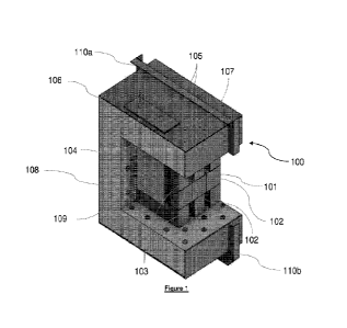
Referring to Figure 1, there is shown the internal structure of an energy
storage device 100 comprising a thermal storage body 101 formed from a
plurality of
miscibility gap alloy thermal storage blocks 102. This thermal storage body
101 is
assembled by the plurality of thermal storage blocks 102 which are milled,
machined,
stacked in an arrangement or the like to provide a plurality of heating
element channels
103 adapted to receive a flow of heat transfer fluids when assembled.
Located adjacent to the thermal storage body in one of the heat transfer
channels is a panel-shaped heating device 104. This heating device is an
electrically
resistive heater with at least one resistive element electrically powered via
electrical
leads or busbars 105. The panel heating device 104 is received in the heat
transfer
channel 103 and secured to the gas-sealed outer-shell 106 of the energy
storage
device 100 by mounting brackets 107. The mounting brackets 107 can be adjusted
to
bring the panel heating device 104 into contact with the thermal storage body
101, or
at a certain distance therefrom, depending on the heat transfer rate and type
(i.e.
radiation, convection and/or conduction) desired by the skilled addressee. The
embodiment shown in Figure 1 comprises a panel-style heating device 104 close
to,
but not in contact with, the thermal storage blocks 102. The bracket-based
mounting
of heating device 104 to the outer-shell 106 allows for independent
adjustment,
extraction and/or replacement thereof. The heating device 104, mounting
bracket 107
and outer-shell 106 comprise appropriate gas-sealing materials such as rubber,
ceramic or soldering gaskets such that the energy storage device 100 is
substantially
gas-tight and thermally insulated during use.
lnsulative material, shown in Figure 1 as thicker insulation panels 108, is
provided on the inner surface of the outer-shell 106. The insulation panels
108 are
constructed and positioned such that when in use, the thermal storage body 101
and
the heat transfer fluids received in the heat transfer channel 103 are
substantially
thermally insulated from the outside atmosphere. The insulation panels 108 are
internally positioned and mounted to the outer shell 106 by pins 109, such
that said
insulation panels 108 are held in abutting engagement.
Finally, the outer-shell 106 comprises weight-bearing frame and feet 110a and
110b that provide substantial structural rigidity and support to the energy
storage
26
CA 03239132 2024- 5- 24
WO 2023/115098
PCT/AU2022/051391
device 100 such that it is able to support its own weight when placed on a
surface, as
well as supporting the weight of at least another energy storage device placed
above
it. In the embodiment shown, the upper feet 110a and lower feet 110b are
shaped in
a complementary fashion such that they can be secured using hook-and-loop
engagement when the energy storage devices 100 are placed on top of each
other.
The energy storage and heat transfer system shown in Figure 2 comprises a
plurality of energy storage devices 100 as a series of subunits in fluid
communication
with each other, collectively forming a large-scale energy storage device
100a. In this
embodiment, this larger storage device 100a is also in fluid communication
with a fluid
pump 112, a heat transfer fluid reservoir 113 and a heat exchanger 114,
forming a
recirculating closed loop arrangement.
In the specific embodiment shown, the fluid pump 112 is a motive fan or blower
adapted to pump substantially gaseous heat transfer fluids such as steam,
hydrocarbons, sub-critical CO2 and/or nitrogen throughout the loop and its
constituent
unit operations. In this regard, the blower is sized as to provide enough head
and flow
throughout both the heat exchanger 114 and energy storage device 100a to
maintain
the flow rate and fluid velocity required for heat transfer and the prevention
of fouling
in both respective unit operations.
In line with the gaseous heat transfer fluid, a gas cooler heat exchanger is
selected in this embodiment as the heat exchanger 114. The heat transfer fluid
heated
by the discharge of thermal energy from the thermal storage body 101 to said
fluid
flowing therethrough is sent to the gas-cooler heat exchanger 114 where it is
brought
into thermal communication with another heat transfer or working fluid by
passing both
fluids through a shell and tube heat exchanger arrangement. The device
comprising
the heat exchanger 114 can be selected and changed depending on the usage and
purpose of the thermal energy discharged from the energy storage device 100a.
For
example, a shell and tube heat exchanger may be used to transfer the energy to
a
working fluid for spinning a turbine for electrical generation, or
alternatively the heat
can be transferred to another heat transfer fluid such as water for heating
industrial
processes via a spray-contact heat exchanger.
27
CA 03239132 2024- 5- 24
WO 2023/115098
PCT/AU2022/051391
A simplified process flow of Figure 2's embodiment is further explained in the
piping and instrumentation diagram (P&ID) shown in Figure 3. As discussed
above,
the energy storage device 100a, blower 112 and heat exchanger 114 are in fluid
connection within a closed loop recirculating the heat transfer fluid. A heat
transfer
fluid reservoir 113 in the form of a tank is also provided, and is fluidically
connected to
channel 115 bypassing the blower 112 of the loop. The valves attached to these
bypass and reservoir feed channels are used to control pumping pressure, as
well as
heat transfer fluid levels inside the closed loop.
Also included in Figure 3 is a coolant-side pump 116 for pumping the at least
another heat transfer or working fluid cooling the heat transfer fluid heated
from the
energy storage device 100a. As labelled in the P&ID and discussed above, the
energy
storage device 100a is not limited to being connected to a heat exchanger, nor
is its
use limited to heating a secondary heat transfer or working fluid. In this
regard, the
skilled addressee would appreciate that the energy storage device 100a would
be able
to directly power a selection of industrial and generation devices, including
but not
limited to at least one steam turbine and a Rankine cycle generator in a
single pass
configuration without a secondary fluid.
Further to the above, various sensors including Flow (Fl), Temperature (TI)
and Pressure (PI) sensors, controllers, motors, heaters and valves are
attached to the
embodiment to monitor and control the charge, discharge and heat transfer
processes.
It is specifically noted that the energy storage device 100a are monitored by
multiple
probes including temperature sensors, while the plurality of heaters forming a
heater
array 104a inserted thereinto are also controlled by a temperature controller
(TC). The
skilled addressee would appreciate that the above components, including the
heater
array 104a can be controlled manually, or using a computer control system in
communication with them. As an example, a feedback control regime for the
thermal
charging process can be implemented using a proportional integral derivative
(PID)
controller in communication with the TO for the heating array 104a and the TI
sensors
of the energy storage device 100a. Furthermore, the temperature, pressure and
flow
sensors, TI, PI and Fl respectively, monitoring the heat transfer fluid can
also be
incorporated into a control regime alongside valves flowing into and out of
the energy
storage device 100a to control the heat transfer fluid flow and heat transfer
rates to
28
CA 03239132 2024- 5- 24
WO 2023/115098
PCT/AU2022/051391
control and determine device conditions during start-up, steady state
operation and
shut down.
Example 2 ¨ Indirect Extraction
Referring to an embodiment shown in Figure 4, the energy storage device 200
can comprise an array of heat exchanger pipes 217 and intermediate material
218
surrounding said array, both received in heat transfer channels 203 formed by
a
plurality of thermal storage blocks 202 comprising the thermal storage body
201. In
use during the discharge phase, the heat transfer fluid is flowed through the
heat
exchanger pipes 217 to conductively receive thermal energy from the thermal
storage
blocks 202, through the intermediate material 218 surrounding said pipes 217.
The intermediate material 218 is formed of dense, highly thermally conductive
material such as silicon carbide or graphite adapted to conduct heat rapidly
and
efficiently between the heat exchanger pipe walls and the miscibility gap
alloy thermal
storage blocks 202. By assembling the thermal storage body 201 to comprise an
alternating layered structure of thermal storage blocks 202 and the heat
transfer
channels 203, the embodiment of Figure 3 eliminates the lossy pipe-to-MGA
interface
and replaces it with a buffer intermediate material 218 that displays improved
thermal
interfacing with both MGA and typical heat exchanger pipe materials such as
copper,
aluminium, boiler steels, stainless steel and Inconel.
Similarly, an array of panel-shaped heating devices 204 are provided adjacent
to the thermal storage body 201 along the heat transfer channels 203a between
the
thermal storage body 201 and the inner-shell 209 of the energy storage device
200.
Similar to the direct fluid transfer embodiment, the heating devices 204 are
powered
by electricity supplied through the leads 205. The inner-shell 209, the
insulation panels
210 and the outer-shell are all constructed such that they provide a
substantially gas-
tight and thermally insulated seal around the thermal storage body 201 to hold
the
stored thermal energy during the storage phase.
Example 3¨ Thermodynamic analyses
The expected thermal performance during the discharge phase of the
embodiment shown in Example 1 is disclosed in Figure 5. From a steady state
internal
29
CA 03239132 2024- 5- 24
WO 2023/115098
PCT/AU2022/051391
temperature of 600 deg. Celsius held during the storage phase, the heat
transfer fluid
circulation is started and maintained at a flow rate such that a relatively
constant
thermal discharge rate of 100 to 130 kW is maintained.
The expected results show that the embodiment described in Example 1 is
able to maintain a relatively constant thermal discharge output, while also
maintaining
discharge fluid temperatures above 500 deg. C for more than 240 minutes (4
hours)
of continuous thermal discharge. In this regard, maintaining 500 deg. C for up
to 4
hours is advantageous, as discharge temperatures in the range of 400 to 700
deg. C
is able to energise and power many industrial and power generation processes.
Compared to thermal storage processes known in the art, the energy storage
arrangement disclosed in Example 1 is able to maintain an operable and useful
temperature for a longer period.
Example 4¨ Scale
Referring to Figure 6, the energy storage device disclosed can be scaled up
in capacity to provide thermal energy for a grid-scale turbine generation
system. In this
embodiment, an array of energy storage devices are in fluid connection to form
a larger
device 300. This larger energy storage device 300 is in further fluid
communication
with a heat recovery steam generator (HRSG) 319 and a circulation fan 320 to
power
a steam turbine 321 in a two-pass configuration. In use, the thermal energy
stored in
the storage device 300 is discharged with the flow of a gaseous heat transfer
fluid
such as steam, air, sub-critical CO2 or nitrogen to heat up and feed the hot
fluid into
the HRSG for recovery and heat transfer to a working fluid (steam in this
case) to
power the turbine. While the skilled addressee would appreciate that the
energy
storage device is scalable to provide various amounts of thermal energy for
power-
generation, the embodiment shown in Figure 6 is scaled to generate 75 MW of
dispatchable electricity from thermally storing intermittently generated
renewable
energy.
Those skilled in the art will appreciate that the invention described herein
is
susceptible to variations and modifications other than those specifically
described. It
is understood that the invention includes all such variations and
modifications which
fall within the spirit and scope of the present invention.
CA 03239132 2024- 5- 24
WO 2023/115098
PCT/AU2022/051391
Example 5¨ Scaled Up Example 2
Another scaled up version of the energy storage device 400 is disclosed in
Figures 7a to 7g. Referring to Figures 7a to 7c, multiple arrays of multiple
thermal
storage blocks 401 each comprising a separate thermal storage body 402, all
contained within a thermally insulated, substantially gas-tight containment
structure
403. In this embodiment, four thermal storage bodies 402 are provided along
the
length of the elongated containment structure 403, such that a stream of
gaseous heat
transfer fluid introduced from the horizontally-facing aperture 404 is flows
through said
bodies via their heat transfer channels 405 located therethrough to the exit
aperture
406 of said containment structure 403. The containment structure 403 is
substantially
thermally insulated by the insulation material 407, which is preferably 300mm
thick.
Multiple heating element ports 408, each connected to a heating element (each
single
port 408 may be connected to a single heating element or multiple ports 408
may
connected to a single heating element or a multiple heating elements may be
connected to a single port 408) are provided the insulating material 407 and
into the
interstitial spaces between each said multiple thermal storage blocks 401 such
that
heating elements inserted therethrough can provide radiant heating during
thermal
charging of the thermal storage bodies 402.
Referring to Figure 7b, the containment structure 403 includes a gas-tight
casing 409 adapted to substantially prevent leakage of the heat transfer fluid
from the
thermal storage device 400. Moreover, the multiple electrical heating element
ports
408 are inserted substantially perpendicular to both the direction of
elongation in the
heating device casing 403 and the general direction of heat transfer fluid
flow. This
perpendicular placement allows the heating element ports 408 to be withdrawn
from
the device when convenient, such as for repairs or according to the level of
thermal
input desired. Furthermore, the use of multiple heating element ports 408
allows the
thermal storage bodies to be thermally charged in even and efficient manner.
Referring to the Figures 7c, the horizontal rows of MGA blocks 401 forming
one of the thermal storage bodies 402 are each positioned in a horizontally
staggered
manner, such that heat transfer channels are defined between the offset faces
of the
hexahedral MGA blocks 401 forming at least three rows. The offset positions of
the
MGA blocks in each row are secured by a combination of "T"-shaped spacers 410
and
31
CA 03239132 2024- 5- 24
WO 2023/115098
PCT/AU2022/051391
horizontal bar spacers 411, each placed between said blocks in a horizontally
alternating manner. Preferably, filler blocks 412 are placed on the ends of
every
second row to support the weight of the MGA blocks 401 on the edge of every
other
row, stabilising the thermal storage body 402. The filler blocks 412 can be
smaller
blocks formed from MGA material, or they can be made of any material to
provide
rigidity to the overall array of blocks.
Depending on the scale of the energy storage device, access to the internal
volume is provided by access ports. In the example illustrated in Figure 7d,
multiple
doors 413 are provided for human access to the internal volume of the device,
and
thus the thermal storage bodies and the MGA blocks forming thereof. Moreover,
the
hexahedral MGA blocks 401 are arranged such that a heat transfer channel for a
radiant heating element via port 408 is provided between said MGA blocks.
Preferably,
the MGA blocks are offset in pairs of two blocks to generate this heat
transfer channel
for heating element placement.
A closer side elevation view of one thermal storage body in Figure 7e and a
plan view provided in Figure 7f show that horizontal bar spacers of two
differing lengths
are provided to secure said MGA blocks 401 in the thermal storage body 402. In
this
regard, both figures illustrate that a longer, "B1"-type bar spacer is placed
across the
length of the pair of hexahedral MGA blocks, while a second shorter, "B2"-type
bar
spacer is adapted and used to secure single MGA blocks at the edges of the
body 402
to allow for said staggered rows and the generation of heat transfer channels
405.
The three types of spacers - "T"-shaped, "B1" and "B2" bar spacers, together
generate heat transfer channels in the form of longitudinal interstitial
spaces and
latitudinal heating element spaces, while also securing the MGA blocks for
structural
rigidity. Moreover, the combination of the bars prevent unnecessary strain of
the MGA
blocks that constitute the thermal storage body, such that they substantially
alleviate
thermal ratchetting.
32
CA 03239132 2024- 5- 24