Some of the information on this Web page has been provided by external sources. The Government of Canada is not responsible for the accuracy, reliability or currency of the information supplied by external sources. Users wishing to rely upon this information should consult directly with the source of the information. Content provided by external sources is not subject to official languages, privacy and accessibility requirements.
Any discrepancies in the text and image of the Claims and Abstract are due to differing posting times. Text of the Claims and Abstract are posted:
| (12) Patent: | (11) CA 1265988 |
|---|---|
| (21) Application Number: | 510012 |
| (54) English Title: | HOLDER FOR FLAMES OF PYROPHORE-CONTAINING FUELS IN HIGH-SPEED AIR |
| (54) French Title: | DISPOSITIF D'ENTRETIEN DES FLAMMES DE CARBURANTS A TENEUR DE PYROPHORE DANS L'AIR A TRES HAUTE VELOCITE |
| Status: | Deemed expired |
| (52) Canadian Patent Classification (CPC): |
|
|---|---|
| (51) International Patent Classification (IPC): |
|
| (72) Inventors : |
|
| (73) Owners : |
|
| (71) Applicants : | |
| (74) Agent: | ASPILA, KALEVI P. |
| (74) Associate agent: | |
| (45) Issued: | 1990-02-20 |
| (22) Filed Date: | 1986-05-26 |
| Availability of licence: | N/A |
| (25) Language of filing: | English |
| Patent Cooperation Treaty (PCT): | No |
|---|
| (30) Application Priority Data: | None |
|---|
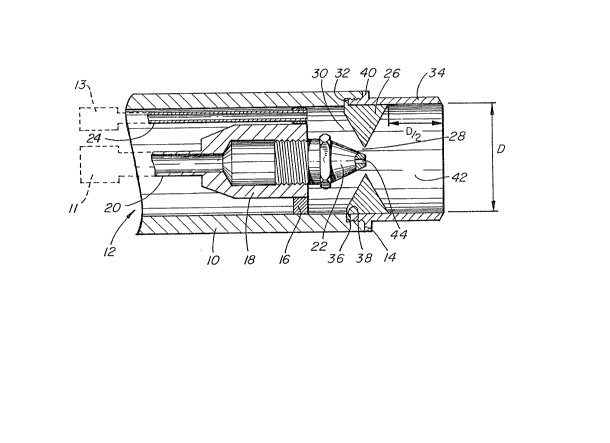
ABSTRACT
An infrared flare is used as a military decoy for
infrared heat seeking missiles. The flare burns a pyrophoric fuel
to provide a good simulation of an aircraft spectral signature.
To minimize blow-out under extreme wind and high altitude
conditions, the flare has an oxygen injector arranged
concentrically around the fuel ejector and a shroud sheltering an
ignition space just downstream of the fuel ejector. The injected
oxygen reacts with a small amount of the flame to produce a pilot
flame in the shroud.
Note: Claims are shown in the official language in which they were submitted.
Note: Descriptions are shown in the official language in which they were submitted.
For a clearer understanding of the status of the application/patent presented on this page, the site Disclaimer , as well as the definitions for Patent , Administrative Status , Maintenance Fee and Payment History should be consulted.
| Title | Date |
|---|---|
| Forecasted Issue Date | 1990-02-20 |
| (22) Filed | 1986-05-26 |
| (45) Issued | 1990-02-20 |
| Deemed Expired | 1996-08-20 |
There is no abandonment history.
| Fee Type | Anniversary Year | Due Date | Amount Paid | Paid Date |
|---|---|---|---|---|
| Application Fee | $0.00 | 1986-05-26 | ||
| Maintenance Fee - Patent - Old Act | 2 | 1992-02-20 | $100.00 | 1991-12-19 |
| Maintenance Fee - Patent - Old Act | 3 | 1993-02-22 | $100.00 | 1993-01-20 |
| Maintenance Fee - Patent - Old Act | 4 | 1994-02-21 | $100.00 | 1994-01-20 |
| Maintenance Fee - Patent - Old Act | 5 | 1995-02-20 | $150.00 | 1995-02-06 |
Note: Records showing the ownership history in alphabetical order.
| Current Owners on Record |
|---|
| HALPIN, JOHN LOUIS |
| MINISTER OF NATIONAL DEFENCE |
| FOSTER, KENNETH DEY |
| Past Owners on Record |
|---|
| None |

