Sélection de la langue

Search

Sommaire du brevet 1265988 

Énoncé de désistement de responsabilité concernant l'information provenant de tiers

Une partie des informations de ce site Web a été fournie par des sources externes. Le gouvernement du Canada n'assume aucune responsabilité concernant la précision, l'actualité ou la fiabilité des informations fournies par les sources externes. Les utilisateurs qui désirent employer cette information devraient consulter directement la source des informations. Le contenu fourni par les sources externes n'est pas assujetti aux exigences sur les langues officielles, la protection des renseignements personnels et l'accessibilité.

Disponibilité de l'Abrégé et des Revendications

L'apparition de différences dans le texte et l'image des Revendications et de l'Abrégé dépend du moment auquel le document est publié. Les textes des Revendications et de l'Abrégé sont affichés :

  • lorsque la demande peut être examinée par le public;
  • lorsque le brevet est émis (délivrance).
(12) Brevet: (11) CA 1265988
(21) Numéro de la demande: 510012
(54) Titre français: DISPOSITIF D'ENTRETIEN DES FLAMMES DE CARBURANTS A TENEUR DE PYROPHORE DANS L'AIR A TRES HAUTE VELOCITE
(54) Titre anglais: HOLDER FOR FLAMES OF PYROPHORE-CONTAINING FUELS IN HIGH-SPEED AIR
Statut: Réputé périmé
Données bibliographiques
(52) Classification canadienne des brevets (CCB):
  • 158/8
(51) Classification internationale des brevets (CIB):
  • F42B 4/26 (2006.01)
(72) Inventeurs :
  • HALPIN, JOHN LOUIS (Canada)
  • FOSTER, KENNETH DEY (Canada)
(73) Titulaires :
  • HALPIN, JOHN LOUIS (Non disponible)
  • MINISTER OF NATIONAL DEFENCE (Canada)
  • FOSTER, KENNETH DEY (Non disponible)
(71) Demandeurs :
(74) Agent: ASPILA, KALEVI P.
(74) Co-agent:
(45) Délivré: 1990-02-20
(22) Date de dépôt: 1986-05-26
Licence disponible: S.O.
(25) Langue des documents déposés: Anglais

Traité de coopération en matière de brevets (PCT): Non

(30) Données de priorité de la demande: S.O.

Abrégés

Abrégé anglais


ABSTRACT

An infrared flare is used as a military decoy for
infrared heat seeking missiles. The flare burns a pyrophoric fuel
to provide a good simulation of an aircraft spectral signature.
To minimize blow-out under extreme wind and high altitude
conditions, the flare has an oxygen injector arranged
concentrically around the fuel ejector and a shroud sheltering an
ignition space just downstream of the fuel ejector. The injected
oxygen reacts with a small amount of the flame to produce a pilot
flame in the shroud.

Revendications

Note : Les revendications sont présentées dans la langue officielle dans laquelle elles ont été soumises.


THE EMBODIMENTS OF THE INVENTION IN WHICH AN EXCLUSIVE PROPERTY
OR PRIVILEGE IS CLAIMED ARE DEFINED AS FOLLOWS:

1. A flare comprising:
a. a supply of pyrophonic fuel;
b. means defining an ignition space for the fuel; said
means comprising an annular housing;
c. a fuel ejector for ejecting a stream of the fuel
into the ignition space;
d. a supply of oxygen;
e. oxygen injection means positioned upstream of said
fuel ejector for injecting a flow of oxygen into said annular
housing and
f. a shroud, said shroud positioned downstream of said
oxygen injection means including means extending radially
inwardly from said housing constricting and deflecting the flow
of oxygen into the vicinity of the fuel ejector so as to cause
spontaneous ignition of the fuel.

2. A flare according to claim 1, wherein the fuel ejector
has a circular ejector orifice.

3. A flare according to claim 2, wherein the oxygen
injector means comprise means providing an annular oxygen
plenum around the fuel ejector and an annular oxygen orifice
concentric with the fuel ejector orifice.

4. A flare according to claim 3, wherein the means
extending radially inwardly comprises oxygen flow directing
means for directing the oxygen flow radially inwardly from


.../2


the annular oxygen orifice into the stream of fuel.

5. A flare according to claim 1, wherein the annular
housing is concentric with and surrounds the fuel ejector.

6. A flare according to claim 5, wherein the oxygen
injector orifice surrounds the ejector.

7. A flare according to claim 6, wherein the shroud is a
concentric extension of the housing.


Description

Note : Les descriptions sont présentées dans la langue officielle dans laquelle elles ont été soumises.

~s~

The present invention relates generall~ to flares and
has particular application to flares that serve as aerial sources
of infrared tIR) radiation for target purposes.
IR flares are used as military decoys for infrared heat
seeking missiles, for defensive or practice purposes. The flares
that are now in use are made from a pyrotechnic magnesium-teflon
composition. However, this composition is not entiEely
satisfactory for defeating more refined missile 3eeker-heads since
the magnesium-teflon flare is a point source and radiates like a
grey body, characteristics that do not adequately simulate the IR
emissions from an aircPaft. These deficiencies coul~ be
ameliorated if a py~ophoric fuel could be used instead of the
traditional pyrotechnic materials.
The main advantages of pyrophoric fuels for flares are:
a) Pyrophoric fuels tespecially the aluminum alkyls)
burn in much the same way as hydrocarbons, thus the infrared
emission from pyrophoric flames is similar to that of kerosene.
Thus, pyrophoric flares would give an infrared spectral signature
much closer to the one given by an aircraft.
~0 b) Pyrophoric flames a~e extended souEces and so the
IR image of a pyrophoric flare would more closely resemble that of
an aircraft.
c) Pyrophoric fuels can use ambient air as an
oxidizer. This allows a large proportion of the flare volume to
be used or fuel.
Despite these advantages, pyrophoric flames have, until
now tended to blow out under extreme wind and high al~itude
conditions. To the best of the applicant's knowledge, 4b4D~-~a-~4

- 1
:


.. ..
' ' . ',' :
: ' ~': . :
` ' - :


~5~8~3

the~e is no pyrophoric fuel dispensing system now available that
can, under these extreme conditions, successfully eject the fuel
into the su~rounding atmosphere to allow combustion ~ith ambient
air while anchoEing the flame to the fuel dispensing system.
According to the pEeSent invention the~e is provided a
flare comprising:
a) a supply of fuel;
b) a fuel ejecto~ for ejecting a stream of the fuel
into an ignition space;
c) a supply of oxygen;
dj oxygen injector means for injecting a flow of
oxygen into the stream of fuel in the ignition space; and
e) a shroud sheltering the ignition space.
A small amount of oxygen injected into the stream of
fuel quickly reacts with some of the fuel and initiates combustion
veEy near the fuel ejector. This forms a pilot flame in the
ignition space which is sheltered fEom the windstream by the
shroud. The Pemaining fuel is thus p~eheated so that it burns
more ~eadily with the surrounding aiE.
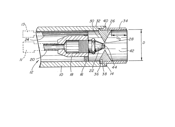
In the accompanying drawing, an exemplaEy embodyment of
the present invention is illustrated, partially in c~oss section.
Referring to the drawing, the flare has a cylindrical
housing 10 with an upstream end 12, only pa~tially shown, that
accommodates a supply of fuel 11 and a supply of oxygen 13.
Slightly upstream from the downstream end 14 of the housing is a
flange 16 that extends across and closes the housing 10. The
flange carrles an internally th~eaded female fitting 1~ connected
to the end o2 a fuel line 20 leading to fuel source 11. An

,


- -
~ ,


~ .

~ 35 ~


o~ifice plug 22 is screwed into the fitting 18 and serves as a
fuel ejector to eject a stream of fuel fEom the end 14 of the
housing 10. The o~ifice plug 22 and the housing 10 are
concent~ic. The orifice 44 of the plug i5 a plain, ci~cula~
o~ifice.
An oxygen line 24 leading from the upstream oxygen
source 13 is also fixed to, and passes through the flange 16.
SuEEounding the downstream end of the oEifice plug 22 is
an oxygen deflector 26~ This i5 an annular element of triangula~
c~oss section that defines an annular oxygen oEifice 28 aEound the
end of the plug 22. The deflector 26 defines, in coope~ation with
the housing 10 and the flange 16, an oxygen plenum 30 suErounding
the oEifice plug 22. The oxygen deflecto~ 26 is held in place by
means of an annular flange 32 on the deflector and a cylindEical
shEoud 34. The shroud is threaded into a threaded counterbore in
the housing to capture the flange 32 between a shoulder 36 on the
housing 10 and the end of 38 of the shroud 34. When the shroud is
scEewed fully into the housing an external annula~ flange 40 on
the shroud abuts the end of the housing. Downstream of the oxygen
deflector 26, the shroud defines an ignition space 42 that has a
length (D/2) that is one half the inte~nal diameter (D) of the
shroud.
In operation, the pyEophoric fuel is ejected through the
o~ifice 44 of the orifice plug 22 into the ignition space 42. An
annulaE flow of oxygen passes from the plenum 30 through the
annular oxygen orifice 28. The deflector 26 directs the oxygen
flow radially inwaEdly into the stream of fuel thus impEoving
atomization of the fuel. The flow rates a~e Eegulated such that


-- 3 --


,
.:

,
,

,
... . .
. . .

~L2~5~3~38

the oxygen injected will burn approximately 3% of the fuel. The
oxygen quickly Eeacts with the fuel and initiates combustion very
near the ejector, thus formirlg a pilot-type flame in the ignition
space 42.
Injection of the oxygen flow as close to the fuel flow
as possible provides for a Eapid mixing of the two streams. FGr
this purpose, the diamete~ of the annulaP oxygen oEifice 28 is
desirably no more than twice the diameteE of the fuel orifice 44.
While one embodiment of the present invention has been
described in the foregoing, it is to be understood that other
embodiments are possible within the scope of the present
invention. Thus, the dimensions and positional ~elationships of
the exemplary embodiment are illustrative only and may be altered
within relatively wide limits while still providing the benefits
of the invention.


r


i`''
~ - 4 -
.

- ~ , . . ... ..
. .
, . . . : .
. ~, .,. : ..
.:
.. ..

Dessin représentatif
Une figure unique qui représente un dessin illustrant l'invention.
États administratifs

Pour une meilleure compréhension de l'état de la demande ou brevet qui figure sur cette page, la rubrique Mise en garde , et les descriptions de Brevet , États administratifs , Taxes périodiques et Historique des paiements devraient être consultées.

États administratifs

Titre Date
Date de délivrance prévu 1990-02-20
(22) Dépôt 1986-05-26
(45) Délivré 1990-02-20
Réputé périmé 1996-08-20

Historique d'abandonnement

Il n'y a pas d'historique d'abandonnement

Historique des paiements

Type de taxes Anniversaire Échéance Montant payé Date payée
Le dépôt d'une demande de brevet 0,00 $ 1986-05-26
Taxe de maintien en état - brevet - ancienne loi 2 1992-02-20 100,00 $ 1991-12-19
Taxe de maintien en état - brevet - ancienne loi 3 1993-02-22 100,00 $ 1993-01-20
Taxe de maintien en état - brevet - ancienne loi 4 1994-02-21 100,00 $ 1994-01-20
Taxe de maintien en état - brevet - ancienne loi 5 1995-02-20 150,00 $ 1995-02-06
Titulaires au dossier

Les titulaires actuels et antérieures au dossier sont affichés en ordre alphabétique.

Titulaires actuels au dossier
HALPIN, JOHN LOUIS
MINISTER OF NATIONAL DEFENCE
FOSTER, KENNETH DEY
Titulaires antérieures au dossier
S.O.
Les propriétaires antérieurs qui ne figurent pas dans la liste des « Propriétaires au dossier » apparaîtront dans d'autres documents au dossier.
Documents

Pour visionner les fichiers sélectionnés, entrer le code reCAPTCHA :


Pour visualiser une image, cliquer sur un lien dans la colonne description du document. Pour télécharger l'image (les images), cliquer l'une ou plusieurs cases à cocher dans la première colonne et ensuite cliquer sur le bouton "Télécharger sélection en format PDF (archive Zip)" ou le bouton "Télécharger sélection (en un fichier PDF fusionné)".

Liste des documents de brevet publiés et non publiés sur la BDBC .

Si vous avez des difficultés à accéder au contenu, veuillez communiquer avec le Centre de services à la clientèle au 1-866-997-1936, ou envoyer un courriel au Centre de service à la clientèle de l'OPIC.


Description du
Document 
Date
(yyyy-mm-dd) 
Nombre de pages   Taille de l'image (Ko) 
Dessins représentatifs 2001-07-03 1 20
Dessins 1993-09-18 1 29
Revendications 1993-09-18 2 50
Abrégé 1993-09-18 1 23
Page couverture 1993-09-18 1 25
Description 1993-09-18 4 154
Taxes 1995-03-01 3 83
Taxes 1995-02-06 3 67
Taxes 1995-03-14 1 15
Taxes 1994-01-20 2 315
Taxes 1993-01-20 3 206
Taxes 1991-12-19 2 82