Language selection

Search

Patent 1285524 Summary

Third-party information liability

Some of the information on this Web page has been provided by external sources. The Government of Canada is not responsible for the accuracy, reliability or currency of the information supplied by external sources. Users wishing to rely upon this information should consult directly with the source of the information. Content provided by external sources is not subject to official languages, privacy and accessibility requirements.

Claims and Abstract availability

Any discrepancies in the text and image of the Claims and Abstract are due to differing posting times. Text of the Claims and Abstract are posted:

  • At the time the application is open to public inspection;
  • At the time of issue of the patent (grant).
(12) Patent: (11) CA 1285524
(21) Application Number: 508314
(54) English Title: CONTAINER CLOSURE
(54) French Title: CAPUCHON POUR RECIPIENT
Status: Deemed expired
Bibliographic Data
(52) Canadian Patent Classification (CPC):
  • 206/31
(51) International Patent Classification (IPC):
  • B65D 41/48 (2006.01)
  • B65D 55/06 (2006.01)
(72) Inventors :
  • BUETTIKER, JEAN PIERRE (Switzerland)
  • KLAIBER, MAX (Switzerland)
(73) Owners :
  • FRIEDRICH SANNER GMBH CO. KG. (United Kingdom)
(71) Applicants :
(74) Agent: NORTON ROSE FULBRIGHT CANADA LLP/S.E.N.C.R.L., S.R.L.
(74) Associate agent:
(45) Issued: 1991-07-02
(22) Filed Date: 1986-05-02
Availability of licence: N/A
(25) Language of filing: English

Patent Cooperation Treaty (PCT): No

(30) Application Priority Data:
Application No. Country/Territory Date
2216/85 Switzerland 1985-05-24

Abstracts

English Abstract


A B S T R A C T

A container closure in the form of a stopper
is provided in which an outer wall engages exterior-
ly of the wall of the container. A tamper-proof
ring is secured to the underside thereof by means of
tear-off webs. The internal cylindrical surface of
the ring comprising tabs directed obliquely inwardly
and in the direction of the opening.


Claims

Note: Claims are shown in the official language in which they were submitted.


The embodiments of the invention in which an
exclusive property or privilege is claimed are
defined as follows;

1. A container and stopper, comprising:
(a) a container having an upper edge which
defines an opening, and flange means formed
at the upper edge of the container around
the opening; and
(b) a stopper having a cover plug, a
tamper-proof ring, and attachment means for
attaching the tamper-proof ring having an
inner surface and tabs attached to said inner
surface, said tabs being formed from a
resilient material and being directed
obliquely inwardly and in the direction of
opening but not engaging said flange means
for retaining the tamper-proof ring on the
container when the cover plug is removed for
the first time and the attachment means
connecting the cover plug and the tamper-proof
ring is broken.

2. The container and stopper according to claim
1, wherein the container has a wall having an
exterior surface and the cover plug comprises a
stopper portion having an outer wall which engages
the exterior surface of the wall of the container,
and wherein the attachment means comprises a
plurality of tear-off webs for securing the
tamper-proof ring to the outer wall of the stopper
portion.


3. A tamper-proof stopper for plugging an opening
in a container having a flange attached to its outer
wall, the stopper comprising:
(a) plug means having a holding segment for
securely holding and sealing the stopper in
the opening of the container, said holding
segment extending into the container and
having an outside diameter corresponding to
a diameter of an inner wall of the container
to seal the stopper in the opening;
(b) a cover member attached to said plug means
and having an annular section extending
beyond the opening of the container to engage
the flange to assist in holding the stopper
in place in the container;
(c) a tamper-proof ring releasably attached to
the annular section of said cover member,
said tamper-proof ring having tab means
connected to an inner surface of said
tamper-proof ring, said tab means being
formed from a resilient material and being
directed obliquely inward away from said inner
surface of said ring in the direction of the
opening of the container but not engaging
said flange, so that said tab means engage
said flange to hold the tamper-proof ring on
the container when said cover member is
removed for the first time; and
(d) attachment means for releasably attaching
said tamper-proof ring to said cover member,
said attachment means being broken when said
cover member is removed from the container
for the first time thereby separating the

- 6 -


cover member from the tamper-proof ring and
providing a visual indication that the
container has been opened.

4. The stopper according to claim 3, wherein the
attachment means comprises a plurality of tear-off
webs for securing the tamper-proof ring to the
annular extension of said cover member.

5. The stopper according to claim 4, wherein the
cover member comprises: a chamber, said chamber
having a drying agent therein; and a resiliently
fitted ring for holding down contents in the
container.

6. The stopper according to claim 3, wherein said
tab means comprises a plurality of tabs, each tab
having a defined segment width; and said cover plug
defines a plurality of recesses in said cover
portion, each of said tabs corresponding to each of
said recesses in number and in said tab segment
width.

7. The stopper according to claim 6 wherein said
tab segment width is about 20 angular degrees.

8. A tamper-proof device comprising:
(a) a container defining an opening and having
an inner wall, an outer wall, and flange
attached to the outer wall near the opening
of the container;
(b) a stopper including a plug means having a
holding segment for securely holding and
sealing the stopper in the opening of the
container, said holding segment extending

- 7 -


into the container and having an outside
diameter corresponding to a diameter of the
inner wall of the container to seal the
stopper in the container;
(c) a cover member attached to said plug means
and having an annular section extending
beyond the container opening to engage the
flange of the container to assist in holding
the stopper in place in said opening;
(d) a tamper-proof ring releasably attached to
the annular section of said cover member,
said tamper-proof ring having tab means
connected to an inner surface of said
tamper-proof ring, said tab means being
formed from a resilient material and being
directed obliquely inward away from said inner
surface of said ring in the direction of the
opening of the container but not engaging
said flange, so that said tab means engage
said flange to hold the tamper-proof ring on
the container when said cover member is
removed for the first time; and
(e) attachment means for releasably attaching
said tamper-proof ring to said cover member,
said attachment means being broken when said
cover member is removed from the container
for the first time thereby separating the
cover member from the tamper-proof ring and
providing a visual indication that the
container has been opened.

-8-


Description

Note: Descriptions are shown in the official language in which they were submitted.


~35~X~

The invention relates to a tamper-proof
closure for a container/closure with a tamper-proof
ring which, in the closed condition, engages the
exterior surface of the wall of the container and
which is torn away the first time the closure is opened.
Tamper-proof closures are known in many
forms. Most frequently, they occur in the form of
screw type closures in which the tamper-proof ring
is retained by the lower edge of the thread.
Proposals have also been made for closure
plugs used, for example, Eor tubes for effervescent
vitamin tablets. For instance, the tamper-proof ring
may be held to the thickened edge or flange on the
tube, in that the inside of the tube is provided
with a bead which, by means of different oblique
surfaces, allows the plug with the ring to be fitted
but the ring is retained upon opening. However,
because of the elasticity of the plastic, such a
closure cannot be made absolutely safe. It is
possible, when opening the closure, to slip the
ring over the edge of the tube without using any
tool and without tearing the ring.
It is therefore the purpose of the invention to
provide tamper-proof closure of the type mentioned above
which provides greater safety against opening without
tearing the tamper-proof ring.


.. ~

-- 1 --

s~

According to the invention, this purpose is
accomplished in that the internal cylindrical surface of
the tamper-proof ring is provided with tabs directed
obliquely inwardly and in the direction of opening, the
said tabs engaging under the edge-bead or flange of the
wall of the container.
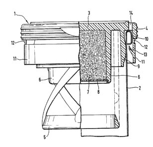
An example of an embodiment o~ the invention is
described hereinafter in conjunction with the drawing
attached hereto.
Figure 1 is a side elevation partly in cross-

section of the tamper-proof closure of the present
invention; and
Figure 2 is a fragmentary top plan view of
the closure shown in Figure 1.
The drawings show a stopper 1 for closing
an effervescent vitamin tablet tube.

The stopper 1 has a flat cover part 3 and
an outer cylindrical wall 4 which engages over the edge
of the tube 2. Peripheral ribs are provided on the
cylindrical outer surface of wall 4, to make the
stopper 1 easier to grip when it is being opened.
The stopper 1 is provided in known fashion with
a resiliently fitted ring 5 which holds down the
content of the tube. The stopper 1 also comprises a
chamber 6 which is filled with a drying agent 7, closed
off by means of a cover 8.
A cylindrical skirt 9, the outside diameter of
which corresponds to the inside diameter of tube 2,
serves to seal the tube from air and moisture.


-- 2

24

In the present case, tube 2 is made of metal,
thus a flange 10 is provided at the upper edge thereof.
In the case of a plastic tube, this would be replaced
by peripheral enlargement of the edge.

outer-wall 4 engages over flange 10 and
secures the stopper 1 to the tube 2.
A tamper-proof ring 11 depends from the wall
4 of the stopper 1. The ring 11 is cylindrical and
the connection to wall 4 is effected by means of thin

webs 12 which require only a small amount of force
to tear.
Eight tabs 13 are mounted to the inside
surface of ring 11. The tabs 13 extend obliquely
inwardly and-radially in the direction of opening.
The tabs 13 engage under flanged edge 10 of tube 2, and
are distributed equidistantly around the periphery
thereof, and each have a segment width corresponding to
approximately 20 angular degrees. Instead o~ the eigh~
tabs provided in the present example, the desired

function may still be obtained by a larger or smaller
number of tabs 13. Like the stopper 1, the tabs 13
are made of plastic and are correspondingly resilient.
When the stopper is opened, tabs 13 act as barbed
hooks and engage under flange 10 of the tube 2. Ring 11
is thus firmly held and webs 12 tear away when the
stopper 1 is removed.


`` ~ 285~a24

In producing tabs 13, the corresponding
tool part engaging behind the tab must be inserted
from above. For this reason, the cover has the same
number of recesses 14.as tabs 13 and the segment
width of the recesses 14 must be the same as the
corresponding width of the tabs 13.

Representative Drawing
A single figure which represents the drawing illustrating the invention.
Administrative Status

For a clearer understanding of the status of the application/patent presented on this page, the site Disclaimer , as well as the definitions for Patent , Administrative Status , Maintenance Fee  and Payment History  should be consulted.

Administrative Status

Title Date
Forecasted Issue Date 1991-07-02
(22) Filed 1986-05-02
(45) Issued 1991-07-02
Deemed Expired 2005-07-04

Abandonment History

There is no abandonment history.

Payment History

Fee Type Anniversary Year Due Date Amount Paid Paid Date
Application Fee $0.00 1986-05-02
Registration of a document - section 124 $0.00 1986-10-08
Maintenance Fee - Patent - Old Act 2 1993-07-02 $100.00 1993-06-28
Maintenance Fee - Patent - Old Act 3 1994-07-04 $100.00 1994-06-23
Maintenance Fee - Patent - Old Act 4 1995-07-03 $100.00 1995-06-27
Maintenance Fee - Patent - Old Act 5 1996-07-02 $150.00 1996-06-26
Maintenance Fee - Patent - Old Act 6 1997-07-02 $150.00 1997-06-30
Maintenance Fee - Patent - Old Act 7 1998-07-02 $150.00 1998-06-29
Maintenance Fee - Patent - Old Act 8 1999-07-02 $150.00 1999-06-23
Maintenance Fee - Patent - Old Act 9 2000-07-03 $150.00 2000-06-19
Maintenance Fee - Patent - Old Act 10 2001-07-02 $200.00 2001-06-08
Maintenance Fee - Patent - Old Act 11 2002-07-02 $200.00 2002-06-06
Maintenance Fee - Patent - Old Act 12 2003-07-02 $200.00 2003-06-19
Owners on Record

Note: Records showing the ownership history in alphabetical order.

Current Owners on Record
FRIEDRICH SANNER GMBH CO. KG.
Past Owners on Record
BUETTIKER, JEAN PIERRE
KLAIBER, MAX
Past Owners that do not appear in the "Owners on Record" listing will appear in other documentation within the application.
Documents

To view selected files, please enter reCAPTCHA code :


To view images, click a link in the Document Description column. To download the documents, select one or more checkboxes in the first column and then click the "Download Selected in PDF format (Zip Archive)" or the "Download Selected as Single PDF" button.

List of published and non-published patent-specific documents on the CPD .

If you have any difficulty accessing content, you can call the Client Service Centre at 1-866-997-1936 or send them an e-mail at CIPO Client Service Centre.


Document
Description 
Date
(yyyy-mm-dd) 
Number of pages   Size of Image (KB) 
Drawings 1993-10-20 1 51
Claims 1993-10-20 4 131
Abstract 1993-10-20 1 12
Cover Page 1993-10-20 1 13
Description 1993-10-20 4 103
Representative Drawing 2001-11-14 1 21
Fees 1996-06-26 1 56
Fees 1995-06-27 1 59
Fees 1994-06-23 1 64
Fees 1993-06-28 1 77