Sélection de la langue

Search

Sommaire du brevet 1285524 

Énoncé de désistement de responsabilité concernant l'information provenant de tiers

Une partie des informations de ce site Web a été fournie par des sources externes. Le gouvernement du Canada n'assume aucune responsabilité concernant la précision, l'actualité ou la fiabilité des informations fournies par les sources externes. Les utilisateurs qui désirent employer cette information devraient consulter directement la source des informations. Le contenu fourni par les sources externes n'est pas assujetti aux exigences sur les langues officielles, la protection des renseignements personnels et l'accessibilité.

Disponibilité de l'Abrégé et des Revendications

L'apparition de différences dans le texte et l'image des Revendications et de l'Abrégé dépend du moment auquel le document est publié. Les textes des Revendications et de l'Abrégé sont affichés :

  • lorsque la demande peut être examinée par le public;
  • lorsque le brevet est émis (délivrance).
(12) Brevet: (11) CA 1285524
(21) Numéro de la demande: 508314
(54) Titre français: CAPUCHON POUR RECIPIENT
(54) Titre anglais: CONTAINER CLOSURE
Statut: Réputé périmé
Données bibliographiques
(52) Classification canadienne des brevets (CCB):
  • 206/31
(51) Classification internationale des brevets (CIB):
  • B65D 41/48 (2006.01)
  • B65D 55/06 (2006.01)
(72) Inventeurs :
  • BUETTIKER, JEAN PIERRE (Suisse)
  • KLAIBER, MAX (Suisse)
(73) Titulaires :
  • FRIEDRICH SANNER GMBH CO. KG. (Royaume-Uni)
(71) Demandeurs :
(74) Agent: NORTON ROSE FULBRIGHT CANADA LLP/S.E.N.C.R.L., S.R.L.
(74) Co-agent:
(45) Délivré: 1991-07-02
(22) Date de dépôt: 1986-05-02
Licence disponible: S.O.
(25) Langue des documents déposés: Anglais

Traité de coopération en matière de brevets (PCT): Non

(30) Données de priorité de la demande:
Numéro de la demande Pays / territoire Date
2216/85 Suisse 1985-05-24

Abrégés

Abrégé anglais


A B S T R A C T

A container closure in the form of a stopper
is provided in which an outer wall engages exterior-
ly of the wall of the container. A tamper-proof
ring is secured to the underside thereof by means of
tear-off webs. The internal cylindrical surface of
the ring comprising tabs directed obliquely inwardly
and in the direction of the opening.

Revendications

Note : Les revendications sont présentées dans la langue officielle dans laquelle elles ont été soumises.


The embodiments of the invention in which an
exclusive property or privilege is claimed are
defined as follows;

1. A container and stopper, comprising:
(a) a container having an upper edge which
defines an opening, and flange means formed
at the upper edge of the container around
the opening; and
(b) a stopper having a cover plug, a
tamper-proof ring, and attachment means for
attaching the tamper-proof ring having an
inner surface and tabs attached to said inner
surface, said tabs being formed from a
resilient material and being directed
obliquely inwardly and in the direction of
opening but not engaging said flange means
for retaining the tamper-proof ring on the
container when the cover plug is removed for
the first time and the attachment means
connecting the cover plug and the tamper-proof
ring is broken.

2. The container and stopper according to claim
1, wherein the container has a wall having an
exterior surface and the cover plug comprises a
stopper portion having an outer wall which engages
the exterior surface of the wall of the container,
and wherein the attachment means comprises a
plurality of tear-off webs for securing the
tamper-proof ring to the outer wall of the stopper
portion.


3. A tamper-proof stopper for plugging an opening
in a container having a flange attached to its outer
wall, the stopper comprising:
(a) plug means having a holding segment for
securely holding and sealing the stopper in
the opening of the container, said holding
segment extending into the container and
having an outside diameter corresponding to
a diameter of an inner wall of the container
to seal the stopper in the opening;
(b) a cover member attached to said plug means
and having an annular section extending
beyond the opening of the container to engage
the flange to assist in holding the stopper
in place in the container;
(c) a tamper-proof ring releasably attached to
the annular section of said cover member,
said tamper-proof ring having tab means
connected to an inner surface of said
tamper-proof ring, said tab means being
formed from a resilient material and being
directed obliquely inward away from said inner
surface of said ring in the direction of the
opening of the container but not engaging
said flange, so that said tab means engage
said flange to hold the tamper-proof ring on
the container when said cover member is
removed for the first time; and
(d) attachment means for releasably attaching
said tamper-proof ring to said cover member,
said attachment means being broken when said
cover member is removed from the container
for the first time thereby separating the

- 6 -


cover member from the tamper-proof ring and
providing a visual indication that the
container has been opened.

4. The stopper according to claim 3, wherein the
attachment means comprises a plurality of tear-off
webs for securing the tamper-proof ring to the
annular extension of said cover member.

5. The stopper according to claim 4, wherein the
cover member comprises: a chamber, said chamber
having a drying agent therein; and a resiliently
fitted ring for holding down contents in the
container.

6. The stopper according to claim 3, wherein said
tab means comprises a plurality of tabs, each tab
having a defined segment width; and said cover plug
defines a plurality of recesses in said cover
portion, each of said tabs corresponding to each of
said recesses in number and in said tab segment
width.

7. The stopper according to claim 6 wherein said
tab segment width is about 20 angular degrees.

8. A tamper-proof device comprising:
(a) a container defining an opening and having
an inner wall, an outer wall, and flange
attached to the outer wall near the opening
of the container;
(b) a stopper including a plug means having a
holding segment for securely holding and
sealing the stopper in the opening of the
container, said holding segment extending

- 7 -


into the container and having an outside
diameter corresponding to a diameter of the
inner wall of the container to seal the
stopper in the container;
(c) a cover member attached to said plug means
and having an annular section extending
beyond the container opening to engage the
flange of the container to assist in holding
the stopper in place in said opening;
(d) a tamper-proof ring releasably attached to
the annular section of said cover member,
said tamper-proof ring having tab means
connected to an inner surface of said
tamper-proof ring, said tab means being
formed from a resilient material and being
directed obliquely inward away from said inner
surface of said ring in the direction of the
opening of the container but not engaging
said flange, so that said tab means engage
said flange to hold the tamper-proof ring on
the container when said cover member is
removed for the first time; and
(e) attachment means for releasably attaching
said tamper-proof ring to said cover member,
said attachment means being broken when said
cover member is removed from the container
for the first time thereby separating the
cover member from the tamper-proof ring and
providing a visual indication that the
container has been opened.

-8-


Description

Note : Les descriptions sont présentées dans la langue officielle dans laquelle elles ont été soumises.

~35~X~

The invention relates to a tamper-proof
closure for a container/closure with a tamper-proof
ring which, in the closed condition, engages the
exterior surface of the wall of the container and
which is torn away the first time the closure is opened.
Tamper-proof closures are known in many
forms. Most frequently, they occur in the form of
screw type closures in which the tamper-proof ring
is retained by the lower edge of the thread.
Proposals have also been made for closure
plugs used, for example, Eor tubes for effervescent
vitamin tablets. For instance, the tamper-proof ring
may be held to the thickened edge or flange on the
tube, in that the inside of the tube is provided
with a bead which, by means of different oblique
surfaces, allows the plug with the ring to be fitted
but the ring is retained upon opening. However,
because of the elasticity of the plastic, such a
closure cannot be made absolutely safe. It is
possible, when opening the closure, to slip the
ring over the edge of the tube without using any
tool and without tearing the ring.
It is therefore the purpose of the invention to
provide tamper-proof closure of the type mentioned above
which provides greater safety against opening without
tearing the tamper-proof ring.


.. ~

-- 1 --

s~

According to the invention, this purpose is
accomplished in that the internal cylindrical surface of
the tamper-proof ring is provided with tabs directed
obliquely inwardly and in the direction of opening, the
said tabs engaging under the edge-bead or flange of the
wall of the container.
An example of an embodiment o~ the invention is
described hereinafter in conjunction with the drawing
attached hereto.
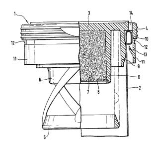
Figure 1 is a side elevation partly in cross-

section of the tamper-proof closure of the present
invention; and
Figure 2 is a fragmentary top plan view of
the closure shown in Figure 1.
The drawings show a stopper 1 for closing
an effervescent vitamin tablet tube.

The stopper 1 has a flat cover part 3 and
an outer cylindrical wall 4 which engages over the edge
of the tube 2. Peripheral ribs are provided on the
cylindrical outer surface of wall 4, to make the
stopper 1 easier to grip when it is being opened.
The stopper 1 is provided in known fashion with
a resiliently fitted ring 5 which holds down the
content of the tube. The stopper 1 also comprises a
chamber 6 which is filled with a drying agent 7, closed
off by means of a cover 8.
A cylindrical skirt 9, the outside diameter of
which corresponds to the inside diameter of tube 2,
serves to seal the tube from air and moisture.


-- 2

24

In the present case, tube 2 is made of metal,
thus a flange 10 is provided at the upper edge thereof.
In the case of a plastic tube, this would be replaced
by peripheral enlargement of the edge.

outer-wall 4 engages over flange 10 and
secures the stopper 1 to the tube 2.
A tamper-proof ring 11 depends from the wall
4 of the stopper 1. The ring 11 is cylindrical and
the connection to wall 4 is effected by means of thin

webs 12 which require only a small amount of force
to tear.
Eight tabs 13 are mounted to the inside
surface of ring 11. The tabs 13 extend obliquely
inwardly and-radially in the direction of opening.
The tabs 13 engage under flanged edge 10 of tube 2, and
are distributed equidistantly around the periphery
thereof, and each have a segment width corresponding to
approximately 20 angular degrees. Instead o~ the eigh~
tabs provided in the present example, the desired

function may still be obtained by a larger or smaller
number of tabs 13. Like the stopper 1, the tabs 13
are made of plastic and are correspondingly resilient.
When the stopper is opened, tabs 13 act as barbed
hooks and engage under flange 10 of the tube 2. Ring 11
is thus firmly held and webs 12 tear away when the
stopper 1 is removed.


`` ~ 285~a24

In producing tabs 13, the corresponding
tool part engaging behind the tab must be inserted
from above. For this reason, the cover has the same
number of recesses 14.as tabs 13 and the segment
width of the recesses 14 must be the same as the
corresponding width of the tabs 13.


Dessin représentatif
Une figure unique qui représente un dessin illustrant l'invention.
États administratifs

Pour une meilleure compréhension de l'état de la demande ou brevet qui figure sur cette page, la rubrique Mise en garde , et les descriptions de Brevet , États administratifs , Taxes périodiques et Historique des paiements devraient être consultées.

États administratifs

Titre Date
Date de délivrance prévu 1991-07-02
(22) Dépôt 1986-05-02
(45) Délivré 1991-07-02
Réputé périmé 2005-07-04

Historique d'abandonnement

Il n'y a pas d'historique d'abandonnement

Historique des paiements

Type de taxes Anniversaire Échéance Montant payé Date payée
Le dépôt d'une demande de brevet 0,00 $ 1986-05-02
Enregistrement de documents 0,00 $ 1986-10-08
Taxe de maintien en état - brevet - ancienne loi 2 1993-07-02 100,00 $ 1993-06-28
Taxe de maintien en état - brevet - ancienne loi 3 1994-07-04 100,00 $ 1994-06-23
Taxe de maintien en état - brevet - ancienne loi 4 1995-07-03 100,00 $ 1995-06-27
Taxe de maintien en état - brevet - ancienne loi 5 1996-07-02 150,00 $ 1996-06-26
Taxe de maintien en état - brevet - ancienne loi 6 1997-07-02 150,00 $ 1997-06-30
Taxe de maintien en état - brevet - ancienne loi 7 1998-07-02 150,00 $ 1998-06-29
Taxe de maintien en état - brevet - ancienne loi 8 1999-07-02 150,00 $ 1999-06-23
Taxe de maintien en état - brevet - ancienne loi 9 2000-07-03 150,00 $ 2000-06-19
Taxe de maintien en état - brevet - ancienne loi 10 2001-07-02 200,00 $ 2001-06-08
Taxe de maintien en état - brevet - ancienne loi 11 2002-07-02 200,00 $ 2002-06-06
Taxe de maintien en état - brevet - ancienne loi 12 2003-07-02 200,00 $ 2003-06-19
Titulaires au dossier

Les titulaires actuels et antérieures au dossier sont affichés en ordre alphabétique.

Titulaires actuels au dossier
FRIEDRICH SANNER GMBH CO. KG.
Titulaires antérieures au dossier
BUETTIKER, JEAN PIERRE
KLAIBER, MAX
Les propriétaires antérieurs qui ne figurent pas dans la liste des « Propriétaires au dossier » apparaîtront dans d'autres documents au dossier.
Documents

Pour visionner les fichiers sélectionnés, entrer le code reCAPTCHA :


Pour visualiser une image, cliquer sur un lien dans la colonne description du document. Pour télécharger l'image (les images), cliquer l'une ou plusieurs cases à cocher dans la première colonne et ensuite cliquer sur le bouton "Télécharger sélection en format PDF (archive Zip)" ou le bouton "Télécharger sélection (en un fichier PDF fusionné)".

Liste des documents de brevet publiés et non publiés sur la BDBC .

Si vous avez des difficultés à accéder au contenu, veuillez communiquer avec le Centre de services à la clientèle au 1-866-997-1936, ou envoyer un courriel au Centre de service à la clientèle de l'OPIC.


Description du
Document 
Date
(yyyy-mm-dd) 
Nombre de pages   Taille de l'image (Ko) 
Dessins 1993-10-20 1 51
Revendications 1993-10-20 4 131
Abrégé 1993-10-20 1 12
Page couverture 1993-10-20 1 13
Description 1993-10-20 4 103
Dessins représentatifs 2001-11-14 1 21
Taxes 1996-06-26 1 56
Taxes 1995-06-27 1 59
Taxes 1994-06-23 1 64
Taxes 1993-06-28 1 77