Language selection

Search

Patent 1295841 Summary

Third-party information liability

Some of the information on this Web page has been provided by external sources. The Government of Canada is not responsible for the accuracy, reliability or currency of the information supplied by external sources. Users wishing to rely upon this information should consult directly with the source of the information. Content provided by external sources is not subject to official languages, privacy and accessibility requirements.

Claims and Abstract availability

Any discrepancies in the text and image of the Claims and Abstract are due to differing posting times. Text of the Claims and Abstract are posted:

  • At the time the application is open to public inspection;
  • At the time of issue of the patent (grant).
(12) Patent: (11) CA 1295841
(21) Application Number: 551830
(54) English Title: BLOWER AND DISCHARGE SPOUT ASSEMBLY
(54) French Title: MACHINE SOUFFLANTE ET GOULOTTE ORIENTABLE POUR ENSILEUSE
Status: Deemed expired
Bibliographic Data
(52) Canadian Patent Classification (CPC):
  • 56/122
(51) International Patent Classification (IPC):
  • A01D 57/10 (2006.01)
  • A01D 43/08 (2006.01)
  • A01D 87/10 (2006.01)
  • A01F 29/12 (2006.01)
  • B65G 53/28 (2006.01)
  • F04D 23/00 (2006.01)
(72) Inventors :
  • DE BUHR, HAROLD EUGENE (United States of America)
  • WILKES, RAYMOND STEELE (United States of America)
(73) Owners :
  • DEERE & COMPANY (United States of America)
(71) Applicants :
(74) Agent: BORDEN LADNER GERVAIS LLP
(74) Associate agent:
(45) Issued: 1992-02-18
(22) Filed Date: 1987-11-13
Availability of licence: N/A
(25) Language of filing: English

Patent Cooperation Treaty (PCT): No

(30) Application Priority Data:
Application No. Country/Territory Date
029,109 United States of America 1987-03-23

Abstracts

English Abstract


BLOWER AND DISCHARGE SPOUT ASSEMBLY
Abstract of the Disclosure
An ensilage harvester blower is provided with a deflector
which directs crop material discharged from the blower along a
path which intersects a curved, crop direction changing,
discharge spout wall surface area at a shallow angle so as to
minimize the normal forces exerted by the discharged material on
the wall surface area.


Claims

Note: Claims are shown in the official language in which they were submitted.


THE EMBODIMENTS OF THE INVENTION IN WHICH AN EXCLUSIVE PROPERTY
OR PRIVILEGE IS CLAIMED ARE DEFINED AS FOLLOWS:

1. In an ensilage harvester blower and discharge spout
assembly including a blower housing having a cylindrical wall,
a blower blade assembly rotatably mounted in the housing and
having blades with radially outer ends disposed in close
proximity to the wall, the housing including, as viewed from
an end thereof, an inlet opening formed in a lower quadrant
thereof and an outlet opening formed in an upper quadrant
thereof spaced approximately one hundred eighty degrees from
the inlet opening, and a discharge spout coupled to the
housing for receiving crop material discharged from the
housing through said outlet opening and having a first spout
section extending upwardly from the housing and coupled to an
arcuately curved second spout section having inner and outer
arcuate wall surfaces with a first wall portion of the first
spout section extending substantially tangentially to the
housing and inner arcuate wall surface, the improvement
comprising: said blower housing having a deflector mounted
transversely thereacross and being joined to the first wall
portion tangentially to and including an arcuate surface
forming a continuation of the cylindrical wall of the housing
and located for directing crop material discharged through
said outlet opening along a path which intersects a surface
area of the outer arcuate wall surface of the second spout
section at a small angle.
2. In an ensilage harvester blower and discharge spout
assembly including a blower housing having a cylindrical wall
containing inlet and outlet openings spaced approximately one
hundred eighty degrees apart and respectively opening
horizontally and vertically, a fan assembly rotatably mounted
in the housing and having blade with radially outer ends
disposed in close proximity to the wall, and a discharge spout
coupled to the housing for receiving crop material discharged
through the outlet opening and having an arcuately curved
elbow spaced above the outlet opening and including inner and
outer arcuate wall surfaces, and a first spout section joined
to the housing and elbow and including a first wall portion

-4-


extending substantially tangentially to the housing and inner
arcuate wall surface, the improvement comprising: a deflector
connected to the first wall portion and including a surface
forming a continuation of the cylindrical wall of the housing
located for directing crop discharge through the outlet
opening along a path which is approximately tangential to the
outer arcuate wall surface of the elbow.

-5-


Description

Note: Descriptions are shown in the official language in which they were submitted.


~5~

BLOWER AND DISCHARGE SPOUT ASSEMBLY
Backaround of the Invention
The present invention relates to ensilage harvesters and
more particularly relates to blower and discharge spout
assemblies for such harvesters.
Wear of blower and discharge spout surfaces is a long-
~ standing problem on forage harvesters. Wear on the spout is
; concentrated in areas where crop material impinges and changes
direction when introduced into the spout by the blower.
Failure of the spout in these localized areas oftennecessitates replacement of an entire spout component.
Summary of the Invent on
According to the present invention there is provided an
improved blower and di~,charge spout combination.
An object of the invention is to provide a blower and
discharge spout combination wherein the impingement on the
discharge spout o~ material discharged from the blower is
minimized.
A more specific object of the invention is to provide a
blower and discharqe spout combination wherein the blower is
designed to direct crop material toward a curved spout surface
so that the material engages the surface at a small angle so
that the material flows or slides with a low normal force.
These and other objects, features and advantages of the
present invention will become apparent to those skilled in the
art from the description which follows and from the drawings.
Brief Description of the Drawinqs
FIG. l is a schematic side elevational view of a blower
and discharge spout assembly showing a typical prior art
design.
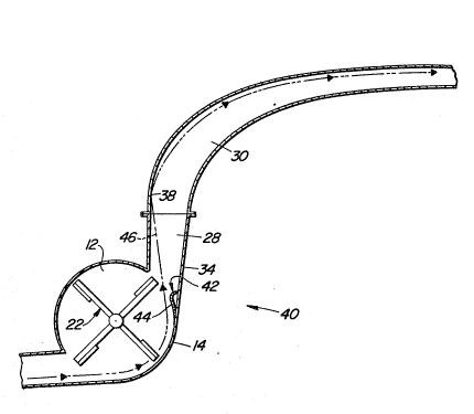
FIG. 2 is a schematic side elevational view of a blower
and discharge spout assembly designed in accordance with the
principles of the present invention.
Description of the Preferred Embodiment
Re~erring now to FIG. 1, there is shown a blower and
discharge spout assembly 10 which is representative of the
prior art. Specifically, the assembly 10 includes a blower
housing 12 including a cylindrical wall 14 having inlet and,
discharge openings 16 and 18 respectively opening horizontally

~5~

and vertically formed substantially one hundred eighty degrees
apart within lower left and upper right quadrants of the
housing, as viewed in FIG. 1. Provided in the housing 12 for
receiving crop material delivered to the inlet opening 16 via
a substantially horizontal conduit 20 and clischarging the
material through the opening 18 is an impeller 22 supported,
by bearings (not shown) located in opposite end walls of the
housing 12, for rotation about an axis Z and including a
plurality of blades or paddles 24 having radially outer ends
lo disposed close to the cylindrical wall 14.
A discharge spout 26 is coupled to the. housing wall 14
for conveying crop material upwardly and away from the
discharge opening 18 and includes a relatively straight first
section 28 and an arcuately curved second section or elbow 30
interconnected at a joint 32. Specifically, the first section
28 is oriented at a slight angle from the vertical and
includes a right wall 34 extending substantially tangentially
to the housiny wall 14 and ~o an inner arcuate wall surface o~
the elbow 30. Crop material discharged into the spout section
28 by the impeller 22 follows a path 36 that parallels the
wall 34 and intersects an arcuately curved, leftward wall
surface area 38 of an outer arcuate wall surface of the second
spout section or elbow 30 at a relatively steep angle~ Thus,
the spout surface area 38 will become worn due to the force of
material impinging thereagainst.
Referring now to FIG. 2, there is shown a blower and
discharge spout assembly 40 which is constructed in most
respects like the previously described assembly 10 and is
given like reference numerals~ Specifically, the assembly 40
includes the impeller or blower 22, housing 12 and discharge
spout sections 28 and 30.
The assembly 40 differs from the assembly 10 in that in
the vicinity of where the spout section wall 34 joins the
housing wall 14, there is provided a blower deflector 42 which
extends transversely across and is joined to the wall 34 and
the ends of the housing 12. The deflector 42 includes an
: arcuate wall 44 which ~orms a short extension of the inner
: :
: : 2
; ~ ,


~ . :

~3~

surface of the cyl.indrical wall 14. The deflector 42 modifies
the trajectory of crop material leaving the housing from that
described above relative to FIG. 1 so that the material
travels along a path 46 that diverges from the wall 34 and
intersects the surface area 38 at a very shallow angle, and,
in fact, is substantially tangential to a bleginning end of the
elbow outer arcuate wall surface that includes the arcuately
curved surface area 38.
Thus, crop material passing through the discharge spout
section 28 flows smoothly along the curvature of an outer
arcuate wall surface sf the discharge spout section or elbow
30.


S~
Representative Drawing
A single figure which represents the drawing illustrating the invention.
Administrative Status

For a clearer understanding of the status of the application/patent presented on this page, the site Disclaimer , as well as the definitions for Patent , Administrative Status , Maintenance Fee  and Payment History  should be consulted.

Administrative Status

Title Date
Forecasted Issue Date 1992-02-18
(22) Filed 1987-11-13
(45) Issued 1992-02-18
Deemed Expired 1999-02-18

Abandonment History

There is no abandonment history.

Payment History

Fee Type Anniversary Year Due Date Amount Paid Paid Date
Application Fee $0.00 1987-11-13
Registration of a document - section 124 $0.00 1988-02-15
Maintenance Fee - Patent - Old Act 2 1994-02-18 $100.00 1994-02-17
Maintenance Fee - Patent - Old Act 3 1995-02-20 $100.00 1995-02-17
Maintenance Fee - Patent - Old Act 4 1996-02-19 $100.00 1996-02-19
Maintenance Fee - Patent - Old Act 5 1997-02-18 $150.00 1997-02-18
Owners on Record

Note: Records showing the ownership history in alphabetical order.

Current Owners on Record
DEERE & COMPANY
Past Owners on Record
DE BUHR, HAROLD EUGENE
WILKES, RAYMOND STEELE
Past Owners that do not appear in the "Owners on Record" listing will appear in other documentation within the application.
Documents

To view selected files, please enter reCAPTCHA code :


To view images, click a link in the Document Description column. To download the documents, select one or more checkboxes in the first column and then click the "Download Selected in PDF format (Zip Archive)" or the "Download Selected as Single PDF" button.

List of published and non-published patent-specific documents on the CPD .

If you have any difficulty accessing content, you can call the Client Service Centre at 1-866-997-1936 or send them an e-mail at CIPO Client Service Centre.


Document
Description 
Date
(yyyy-mm-dd) 
Number of pages   Size of Image (KB) 
Drawings 1993-10-27 1 41
Claims 1993-10-27 2 83
Abstract 1993-10-27 1 14
Cover Page 1993-10-27 1 16
Description 1993-10-27 3 146
Representative Drawing 2000-08-02 1 9
Fees 1995-02-17 1 54
Fees 1994-02-17 1 64
Fees 1997-02-17 1 60
Fees 1996-02-19 1 60