Sélection de la langue

Search

Sommaire du brevet 1295841 

Énoncé de désistement de responsabilité concernant l'information provenant de tiers

Une partie des informations de ce site Web a été fournie par des sources externes. Le gouvernement du Canada n'assume aucune responsabilité concernant la précision, l'actualité ou la fiabilité des informations fournies par les sources externes. Les utilisateurs qui désirent employer cette information devraient consulter directement la source des informations. Le contenu fourni par les sources externes n'est pas assujetti aux exigences sur les langues officielles, la protection des renseignements personnels et l'accessibilité.

Disponibilité de l'Abrégé et des Revendications

L'apparition de différences dans le texte et l'image des Revendications et de l'Abrégé dépend du moment auquel le document est publié. Les textes des Revendications et de l'Abrégé sont affichés :

  • lorsque la demande peut être examinée par le public;
  • lorsque le brevet est émis (délivrance).
(12) Brevet: (11) CA 1295841
(21) Numéro de la demande: 551830
(54) Titre français: MACHINE SOUFFLANTE ET GOULOTTE ORIENTABLE POUR ENSILEUSE
(54) Titre anglais: BLOWER AND DISCHARGE SPOUT ASSEMBLY
Statut: Réputé périmé
Données bibliographiques
(52) Classification canadienne des brevets (CCB):
  • 56/122
(51) Classification internationale des brevets (CIB):
  • A01D 57/10 (2006.01)
  • A01D 43/08 (2006.01)
  • A01D 87/10 (2006.01)
  • A01F 29/12 (2006.01)
  • B65G 53/28 (2006.01)
  • F04D 23/00 (2006.01)
(72) Inventeurs :
  • DE BUHR, HAROLD EUGENE (Etats-Unis d'Amérique)
  • WILKES, RAYMOND STEELE (Etats-Unis d'Amérique)
(73) Titulaires :
  • DEERE & COMPANY (Etats-Unis d'Amérique)
(71) Demandeurs :
(74) Agent: BORDEN LADNER GERVAIS LLP
(74) Co-agent:
(45) Délivré: 1992-02-18
(22) Date de dépôt: 1987-11-13
Licence disponible: S.O.
(25) Langue des documents déposés: Anglais

Traité de coopération en matière de brevets (PCT): Non

(30) Données de priorité de la demande:
Numéro de la demande Pays / territoire Date
029,109 Etats-Unis d'Amérique 1987-03-23

Abrégés

Abrégé anglais


BLOWER AND DISCHARGE SPOUT ASSEMBLY
Abstract of the Disclosure
An ensilage harvester blower is provided with a deflector
which directs crop material discharged from the blower along a
path which intersects a curved, crop direction changing,
discharge spout wall surface area at a shallow angle so as to
minimize the normal forces exerted by the discharged material on
the wall surface area.

Revendications

Note : Les revendications sont présentées dans la langue officielle dans laquelle elles ont été soumises.


THE EMBODIMENTS OF THE INVENTION IN WHICH AN EXCLUSIVE PROPERTY
OR PRIVILEGE IS CLAIMED ARE DEFINED AS FOLLOWS:

1. In an ensilage harvester blower and discharge spout
assembly including a blower housing having a cylindrical wall,
a blower blade assembly rotatably mounted in the housing and
having blades with radially outer ends disposed in close
proximity to the wall, the housing including, as viewed from
an end thereof, an inlet opening formed in a lower quadrant
thereof and an outlet opening formed in an upper quadrant
thereof spaced approximately one hundred eighty degrees from
the inlet opening, and a discharge spout coupled to the
housing for receiving crop material discharged from the
housing through said outlet opening and having a first spout
section extending upwardly from the housing and coupled to an
arcuately curved second spout section having inner and outer
arcuate wall surfaces with a first wall portion of the first
spout section extending substantially tangentially to the
housing and inner arcuate wall surface, the improvement
comprising: said blower housing having a deflector mounted
transversely thereacross and being joined to the first wall
portion tangentially to and including an arcuate surface
forming a continuation of the cylindrical wall of the housing
and located for directing crop material discharged through
said outlet opening along a path which intersects a surface
area of the outer arcuate wall surface of the second spout
section at a small angle.
2. In an ensilage harvester blower and discharge spout
assembly including a blower housing having a cylindrical wall
containing inlet and outlet openings spaced approximately one
hundred eighty degrees apart and respectively opening
horizontally and vertically, a fan assembly rotatably mounted
in the housing and having blade with radially outer ends
disposed in close proximity to the wall, and a discharge spout
coupled to the housing for receiving crop material discharged
through the outlet opening and having an arcuately curved
elbow spaced above the outlet opening and including inner and
outer arcuate wall surfaces, and a first spout section joined
to the housing and elbow and including a first wall portion

-4-


extending substantially tangentially to the housing and inner
arcuate wall surface, the improvement comprising: a deflector
connected to the first wall portion and including a surface
forming a continuation of the cylindrical wall of the housing
located for directing crop discharge through the outlet
opening along a path which is approximately tangential to the
outer arcuate wall surface of the elbow.

-5-


Description

Note : Les descriptions sont présentées dans la langue officielle dans laquelle elles ont été soumises.


~5~

BLOWER AND DISCHARGE SPOUT ASSEMBLY
Backaround of the Invention
The present invention relates to ensilage harvesters and
more particularly relates to blower and discharge spout
assemblies for such harvesters.
Wear of blower and discharge spout surfaces is a long-
~ standing problem on forage harvesters. Wear on the spout is
; concentrated in areas where crop material impinges and changes
direction when introduced into the spout by the blower.
Failure of the spout in these localized areas oftennecessitates replacement of an entire spout component.
Summary of the Invent on
According to the present invention there is provided an
improved blower and di~,charge spout combination.
An object of the invention is to provide a blower and
discharge spout combination wherein the impingement on the
discharge spout o~ material discharged from the blower is
minimized.
A more specific object of the invention is to provide a
blower and discharqe spout combination wherein the blower is
designed to direct crop material toward a curved spout surface
so that the material engages the surface at a small angle so
that the material flows or slides with a low normal force.
These and other objects, features and advantages of the
present invention will become apparent to those skilled in the
art from the description which follows and from the drawings.
Brief Description of the Drawinqs
FIG. l is a schematic side elevational view of a blower
and discharge spout assembly showing a typical prior art
design.
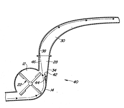
FIG. 2 is a schematic side elevational view of a blower
and discharge spout assembly designed in accordance with the
principles of the present invention.
Description of the Preferred Embodiment
Re~erring now to FIG. 1, there is shown a blower and
discharge spout assembly 10 which is representative of the
prior art. Specifically, the assembly 10 includes a blower
housing 12 including a cylindrical wall 14 having inlet and,
discharge openings 16 and 18 respectively opening horizontally

~5~

and vertically formed substantially one hundred eighty degrees
apart within lower left and upper right quadrants of the
housing, as viewed in FIG. 1. Provided in the housing 12 for
receiving crop material delivered to the inlet opening 16 via
a substantially horizontal conduit 20 and clischarging the
material through the opening 18 is an impeller 22 supported,
by bearings (not shown) located in opposite end walls of the
housing 12, for rotation about an axis Z and including a
plurality of blades or paddles 24 having radially outer ends
lo disposed close to the cylindrical wall 14.
A discharge spout 26 is coupled to the. housing wall 14
for conveying crop material upwardly and away from the
discharge opening 18 and includes a relatively straight first
section 28 and an arcuately curved second section or elbow 30
interconnected at a joint 32. Specifically, the first section
28 is oriented at a slight angle from the vertical and
includes a right wall 34 extending substantially tangentially
to the housiny wall 14 and ~o an inner arcuate wall surface o~
the elbow 30. Crop material discharged into the spout section
28 by the impeller 22 follows a path 36 that parallels the
wall 34 and intersects an arcuately curved, leftward wall
surface area 38 of an outer arcuate wall surface of the second
spout section or elbow 30 at a relatively steep angle~ Thus,
the spout surface area 38 will become worn due to the force of
material impinging thereagainst.
Referring now to FIG. 2, there is shown a blower and
discharge spout assembly 40 which is constructed in most
respects like the previously described assembly 10 and is
given like reference numerals~ Specifically, the assembly 40
includes the impeller or blower 22, housing 12 and discharge
spout sections 28 and 30.
The assembly 40 differs from the assembly 10 in that in
the vicinity of where the spout section wall 34 joins the
housing wall 14, there is provided a blower deflector 42 which
extends transversely across and is joined to the wall 34 and
the ends of the housing 12. The deflector 42 includes an
: arcuate wall 44 which ~orms a short extension of the inner
: :
: : 2
; ~ ,


~ . :

~3~

surface of the cyl.indrical wall 14. The deflector 42 modifies
the trajectory of crop material leaving the housing from that
described above relative to FIG. 1 so that the material
travels along a path 46 that diverges from the wall 34 and
intersects the surface area 38 at a very shallow angle, and,
in fact, is substantially tangential to a bleginning end of the
elbow outer arcuate wall surface that includes the arcuately
curved surface area 38.
Thus, crop material passing through the discharge spout
section 28 flows smoothly along the curvature of an outer
arcuate wall surface sf the discharge spout section or elbow
30.


S~
Dessin représentatif
Une figure unique qui représente un dessin illustrant l'invention.
États administratifs

Pour une meilleure compréhension de l'état de la demande ou brevet qui figure sur cette page, la rubrique Mise en garde , et les descriptions de Brevet , États administratifs , Taxes périodiques et Historique des paiements devraient être consultées.

États administratifs

Titre Date
Date de délivrance prévu 1992-02-18
(22) Dépôt 1987-11-13
(45) Délivré 1992-02-18
Réputé périmé 1999-02-18

Historique d'abandonnement

Il n'y a pas d'historique d'abandonnement

Historique des paiements

Type de taxes Anniversaire Échéance Montant payé Date payée
Le dépôt d'une demande de brevet 0,00 $ 1987-11-13
Enregistrement de documents 0,00 $ 1988-02-15
Taxe de maintien en état - brevet - ancienne loi 2 1994-02-18 100,00 $ 1994-02-17
Taxe de maintien en état - brevet - ancienne loi 3 1995-02-20 100,00 $ 1995-02-17
Taxe de maintien en état - brevet - ancienne loi 4 1996-02-19 100,00 $ 1996-02-19
Taxe de maintien en état - brevet - ancienne loi 5 1997-02-18 150,00 $ 1997-02-18
Titulaires au dossier

Les titulaires actuels et antérieures au dossier sont affichés en ordre alphabétique.

Titulaires actuels au dossier
DEERE & COMPANY
Titulaires antérieures au dossier
DE BUHR, HAROLD EUGENE
WILKES, RAYMOND STEELE
Les propriétaires antérieurs qui ne figurent pas dans la liste des « Propriétaires au dossier » apparaîtront dans d'autres documents au dossier.
Documents

Pour visionner les fichiers sélectionnés, entrer le code reCAPTCHA :


Pour visualiser une image, cliquer sur un lien dans la colonne description du document. Pour télécharger l'image (les images), cliquer l'une ou plusieurs cases à cocher dans la première colonne et ensuite cliquer sur le bouton "Télécharger sélection en format PDF (archive Zip)" ou le bouton "Télécharger sélection (en un fichier PDF fusionné)".

Liste des documents de brevet publiés et non publiés sur la BDBC .

Si vous avez des difficultés à accéder au contenu, veuillez communiquer avec le Centre de services à la clientèle au 1-866-997-1936, ou envoyer un courriel au Centre de service à la clientèle de l'OPIC.


Description du
Document 
Date
(yyyy-mm-dd) 
Nombre de pages   Taille de l'image (Ko) 
Dessins 1993-10-27 1 41
Revendications 1993-10-27 2 83
Abrégé 1993-10-27 1 14
Page couverture 1993-10-27 1 16
Description 1993-10-27 3 146
Dessins représentatifs 2000-08-02 1 9
Taxes 1995-02-17 1 54
Taxes 1994-02-17 1 64
Taxes 1997-02-17 1 60
Taxes 1996-02-19 1 60