Language selection

Search

Patent 1311947 Summary

Third-party information liability

Some of the information on this Web page has been provided by external sources. The Government of Canada is not responsible for the accuracy, reliability or currency of the information supplied by external sources. Users wishing to rely upon this information should consult directly with the source of the information. Content provided by external sources is not subject to official languages, privacy and accessibility requirements.

Claims and Abstract availability

Any discrepancies in the text and image of the Claims and Abstract are due to differing posting times. Text of the Claims and Abstract are posted:

  • At the time the application is open to public inspection;
  • At the time of issue of the patent (grant).
(12) Patent: (11) CA 1311947
(21) Application Number: 536690
(54) English Title: SCREW GUN AUTOMATIC FEED
(54) French Title: TOURNEVIS A ALIMENTATION AUTOMATIQUE
Status: Deemed expired
Bibliographic Data
(52) Canadian Patent Classification (CPC):
  • 81/26
(51) International Patent Classification (IPC):
  • B25B 23/06 (2006.01)
(72) Inventors :
  • GOULD, FREDERICK H., JR. (United States of America)
  • SPECTOR, GEORGE (United States of America)
(73) Owners :
  • GOULD, FREDERICK H., JR. (United States of America)
  • SPECTOR, GEORGE (United States of America)
(71) Applicants :
(74) Agent:
(74) Associate agent:
(45) Issued: 1992-12-29
(22) Filed Date: 1987-05-08
Availability of licence: Yes
(25) Language of filing: English

Patent Cooperation Treaty (PCT): No

(30) Application Priority Data: None

Abstracts

English Abstract


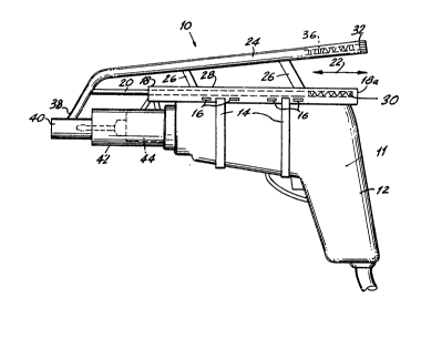
ABSTRACT OF THE DISCLOSURE

An automatic feed screws driver for continuously driving
a plurality of screws and adaptable for mounting on a
conventional drill and which includes a stationary tube
mounted on the drill housing, a stationary sleeve mounted on
the barrel of the drill, a spring pressed slide sleeve biased
outwardly within the stationary sleeve, a gravity feed tube in
communication with the slide sleeve and is slidably mounted on
the stationary tube. A spring loaded knife is disposed in the
slide sleeve for separating the screws from a tape attached
thereto. An element is provided for varying the spring
pressure on the slide sleeve.


-9-


Claims

Note: Claims are shown in the official language in which they were submitted.


CLAIMS

What is claimed is:

1. An automatic feed screw driver and gravity fed
screws provided in said driver adapted for mounting on a
conventional drill having a screw driver, comprising:
(a) means for removeably mounting the automatic feed
screw driver on a drill having a barrel projecting from a
housing;
(b) means for guiding the screw driver to engage a
screw, one at a time;
(c) means for guiding and feeding the said screws one at
a time for engagement with said screw driver, wherein said
mounting means include a stationary tube mounted on said drill
housing and wherein said means for engaging said screws with
said screw driver include a stationary sleeve mounted on said
barrel and a spring pressed slide sleeve biased outwardly in
said stationary sleeve and wherein said means for guiding and
feeding the plurality of screws include an inclined gravity
feed tube communicating with a forward end of said slide
sleeve and terminating at an upper rearward end with a
threaded cap, said threaded cap being removeably mounted so
that said plurality of screws may be introduced therein; said
plurality of screws being attached to each other by a tape
wherein said stationary sleeve is affixed to said stationary


-6-


tube and wherein said gravity feed tube is slidably mounted on
said stationary tube;
(d) means for separating a screw from the plurality of
screws which includes a spring loaded knife disposed in said
slide sleeve including means to be activated when said slide
sleeve is forced inward within said stationary sleeve by
manual pressure of the operator against said housing.


2. A driver as in claim 1, wherein said stationary tube
is mounted on the top of said housing and includes a guide
slot to receive slidingly therein supports depending from said
gravity feed tube.


3. An automatic feed screw driver and gravity feed
screws provided in said driver adapted for mounting on a
conventional drill having a screw driver, comprising:
(a) means for removeably mounting the automatic feed
screw driver on a drill having a barrel projecting from a
housing;
(b) means for guiding the screw driver to engage a
screw, one at a time;
(c) means for guiding and feeding the said screws one at
a time for engagement with said screw driver, wherein said
mounting means include a stationary tube mounted on said drill
housing and wherein said means for engaging said screws with
said screw driver include a stationary sleeve mounted on said
barrel and a spring pressed slide sleeve biased outwardly in


-7-


said stationary sleeve and wherein said means for guiding and
feeding the plurality of screws include an inclined gravity
feed tube communicating with a forward end of said slide
sleeve and terminating at an upper rearward end with a
threaded cap, said threaded cap being removably mounted so
that said plurality of screws may be introduced therein; said
plurality of screws being attached to each other by a tape
wherein said stationary sleeve is affixed to said stationary
tube and wherein said gravity feed tube is slidably mounted on
said stationary tube, wherein said gravity feed tube has a
forward portion of greater inclination which intersects a bore
in said slide sleeve, including means on said slide sleeve for
varying the spring pressure on said slide sleeve and wherein
said stationary tube has a spring mounted therein biasing said
feed tube forwardly.


-8-

Description

Note: Descriptions are shown in the official language in which they were submitted.


~; D ~ ~ If


` i31~7


The present invention relates to an automatic screw feed
tool. More particularly, it relates to an automatic screw
feed tool using a driving unit.
Automatic screw feed tools of the above-mentioned
general type are known in the art. For example, U.S. patent
Number 2,670,770 to Potterton relates to an automatic screw
driver which reguires the insertion of individual screws.
Other examples, U.S. patent number 2,777,484 to Groneman and
U.S. patent Number 3,960,191 to Murray also relate to
automatic screw drives which require the insertion of
individual screws.
Thus, the prior art teaches automatic screw drivers
which reguire the constant insertion of individual screws.


1:


-1-
~,


` 13119~


SUMMARY QF_THE INyENTIQN


Accordingly, it is the primary object of the present
invention to provide an automatic screw feed tool that avoîds
the disadvantages of the prior art.
Another object of the present invention is to provide an
automatic screw feed tool utilizing a "belt feed" arrangement
of the screws through a hollow feed tube.
Yet another of the invention is to provide an automatic
screw feed tool which is adaptable to a conventional drill.
Still another object of the present invention is to
, provide an automatic screw feed tool which is adjustable
mounted so as to fit any conventional drill.
Further objects of the invention will appear as the
description proceed~.
To the accomplishment of the above and related objects,
this invention may be embodied in the form illustrated in the
accompanying drawings, attention being called to the fact,
however, that the drawings are illustrative only and that
changes may be made in the specific construction illustrated
and described within the scope of the appended claims.

~" ' .


`1~


-2-


i

.

` i3119~7


The figures in the drawings are briefly described as
follows:

Figure 1 is a side elevational view of the invention and
associated driving tool at rest position;

Figure 2 iB a enlarged cross sectional view of the front
portion of the invention corresponding to the position in
Figure 1; and
:;
Figure 3 is an enlarged cross sectional view of the
front portion of a modification showing an adjustment spring
lo~ded ring and a knife for cutting the tape between the
screws with the driving tool starting its driving position.

,,

DETAILED DESCRIPTION OF THE PREFERRED EMBODIMENTS

Referring now to Figures 1, the automatic screw feed
tool of the present invention is shown generally at 10 mounted
to a conventional drill 12. The automatic screw feed tool 10
~: is mounted to the drill 12 by straps 14 that pass through
slots 16 in the stationary tube 18. A slide shaft 20 is
movable within the stationary tube 18 in direction of arrows
-~ : 20 22. A feed tube 24 is attached to the slide shaft 20 and

~,~
~ -3-

'''~ , ~

131~ 9~7


moves therewith. Supports 26 riding in a slot 28 further
support the feed tube 24.
The stationary tube 18 is closed at a one end 18a and
biases the slide shaft 20 with a spring 30. The feed tube 24
is closed at a one end 32 by a threaded cap 34 which is
removable to load screws 36. The other end 38 of the feed
tube 24 is connected to a sleeve 40 which is movable in a
stationary sleeve 42 which mounts over chuck 44 of the dxill
12.
The feeding arrangement is shown in greater detail in
Figure 2. The screws 36 are attached to a tape 46 and ride in
the interior of the feed tube 24. A spring 48 biases the
slide sleeve 40 in the extended position.
The screw 36 are fed via the tape 46 which is inside the
feed tube 24. the tape 46 with the screws 36 mounted therein
is inserted into the feed tube 24 by removing the threaded cap
~34~ The feed tube 24 is guided for longitudinal movement by --
~ ,,
the ~tationary tube 18 mounted on the drill 12. The
stationary tube 18 may be adjusted longitudinally relative to
the drill 12 by means of the slots 16 holding the straps 14.
In operation, the tool 10 is pressed against a working
;~ surface which forces the slide sleeve 40 to move inward of the
~tationary sleeve 42 against the bia~ing action of the spring
48 whereby the driver 47 is forced to engage the lead screw 36
' and drive it forward against the work surface. the driving
i forward action severs the lead screw 36 from the tape 46 and
:,
the screw 36 is then driven into the work surface. relieving
' ~

~ -4-

;~ , , , - , .

~ 13il9~7


the pressure of the tool 10 from the work surface causes
retraction of the driver 47 and permits the next screw 36 to
descend into the barrel of the slide sleeve 40.
An alternate embodiment is shown in Figure 3, where a
spring loaded knife 50 is forced inward to cut the tape 46 as
the driver 47 engages the lead screw 36 when the tool 10 is
pressed against the work surface. Additionally, an adjustment
ring 52 can be moved longitudinally in a slot 54 to change the
spring pressure of the spring 48, against the slide sleeve 40.
While certain novel features of this invention have been
shown and described and are pointed out in the annexed claims,
it will be understood that various omissions, substitutions
and changes in the forms and details of the device illustrated
and in its operation can be made by those skilled in the art
without departing from the spirit of the invention.

:


:, .


,,

f,
!~:
I f
.
~i" ~ :
f, ~ ~

~ 5-

I;
. I
1 .

Representative Drawing
A single figure which represents the drawing illustrating the invention.
Administrative Status

For a clearer understanding of the status of the application/patent presented on this page, the site Disclaimer , as well as the definitions for Patent , Administrative Status , Maintenance Fee  and Payment History  should be consulted.

Administrative Status

Title Date
Forecasted Issue Date 1992-12-29
(22) Filed 1987-05-08
(45) Issued 1992-12-29
Deemed Expired 1995-06-29

Abandonment History

There is no abandonment history.

Payment History

Fee Type Anniversary Year Due Date Amount Paid Paid Date
Application Fee $0.00 1987-05-08
Owners on Record

Note: Records showing the ownership history in alphabetical order.

Current Owners on Record
GOULD, FREDERICK H., JR.
SPECTOR, GEORGE
Past Owners on Record
None
Past Owners that do not appear in the "Owners on Record" listing will appear in other documentation within the application.
Documents

To view selected files, please enter reCAPTCHA code :


To view images, click a link in the Document Description column. To download the documents, select one or more checkboxes in the first column and then click the "Download Selected in PDF format (Zip Archive)" or the "Download Selected as Single PDF" button.

List of published and non-published patent-specific documents on the CPD .

If you have any difficulty accessing content, you can call the Client Service Centre at 1-866-997-1936 or send them an e-mail at CIPO Client Service Centre.


Document
Description 
Date
(yyyy-mm-dd) 
Number of pages   Size of Image (KB) 
Drawings 1993-11-09 1 37
Claims 1993-11-09 3 90
Abstract 1993-11-09 1 19
Cover Page 1993-11-09 1 13
Description 1993-11-09 5 146
Representative Drawing 2000-08-08 1 11