Sélection de la langue

Search

Sommaire du brevet 1311947 

Énoncé de désistement de responsabilité concernant l'information provenant de tiers

Une partie des informations de ce site Web a été fournie par des sources externes. Le gouvernement du Canada n'assume aucune responsabilité concernant la précision, l'actualité ou la fiabilité des informations fournies par les sources externes. Les utilisateurs qui désirent employer cette information devraient consulter directement la source des informations. Le contenu fourni par les sources externes n'est pas assujetti aux exigences sur les langues officielles, la protection des renseignements personnels et l'accessibilité.

Disponibilité de l'Abrégé et des Revendications

L'apparition de différences dans le texte et l'image des Revendications et de l'Abrégé dépend du moment auquel le document est publié. Les textes des Revendications et de l'Abrégé sont affichés :

  • lorsque la demande peut être examinée par le public;
  • lorsque le brevet est émis (délivrance).
(12) Brevet: (11) CA 1311947
(21) Numéro de la demande: 536690
(54) Titre français: TOURNEVIS A ALIMENTATION AUTOMATIQUE
(54) Titre anglais: SCREW GUN AUTOMATIC FEED
Statut: Réputé périmé
Données bibliographiques
(52) Classification canadienne des brevets (CCB):
  • 81/26
(51) Classification internationale des brevets (CIB):
  • B25B 23/06 (2006.01)
(72) Inventeurs :
  • GOULD, FREDERICK H., JR. (Etats-Unis d'Amérique)
  • SPECTOR, GEORGE (Etats-Unis d'Amérique)
(73) Titulaires :
  • GOULD, FREDERICK H., JR. (Etats-Unis d'Amérique)
  • SPECTOR, GEORGE (Etats-Unis d'Amérique)
(71) Demandeurs :
(74) Agent:
(74) Co-agent:
(45) Délivré: 1992-12-29
(22) Date de dépôt: 1987-05-08
Licence disponible: Oui
(25) Langue des documents déposés: Anglais

Traité de coopération en matière de brevets (PCT): Non

(30) Données de priorité de la demande: S.O.

Abrégés

Abrégé anglais


ABSTRACT OF THE DISCLOSURE

An automatic feed screws driver for continuously driving
a plurality of screws and adaptable for mounting on a
conventional drill and which includes a stationary tube
mounted on the drill housing, a stationary sleeve mounted on
the barrel of the drill, a spring pressed slide sleeve biased
outwardly within the stationary sleeve, a gravity feed tube in
communication with the slide sleeve and is slidably mounted on
the stationary tube. A spring loaded knife is disposed in the
slide sleeve for separating the screws from a tape attached
thereto. An element is provided for varying the spring
pressure on the slide sleeve.


-9-

Revendications

Note : Les revendications sont présentées dans la langue officielle dans laquelle elles ont été soumises.


CLAIMS

What is claimed is:

1. An automatic feed screw driver and gravity fed
screws provided in said driver adapted for mounting on a
conventional drill having a screw driver, comprising:
(a) means for removeably mounting the automatic feed
screw driver on a drill having a barrel projecting from a
housing;
(b) means for guiding the screw driver to engage a
screw, one at a time;
(c) means for guiding and feeding the said screws one at
a time for engagement with said screw driver, wherein said
mounting means include a stationary tube mounted on said drill
housing and wherein said means for engaging said screws with
said screw driver include a stationary sleeve mounted on said
barrel and a spring pressed slide sleeve biased outwardly in
said stationary sleeve and wherein said means for guiding and
feeding the plurality of screws include an inclined gravity
feed tube communicating with a forward end of said slide
sleeve and terminating at an upper rearward end with a
threaded cap, said threaded cap being removeably mounted so
that said plurality of screws may be introduced therein; said
plurality of screws being attached to each other by a tape
wherein said stationary sleeve is affixed to said stationary


-6-


tube and wherein said gravity feed tube is slidably mounted on
said stationary tube;
(d) means for separating a screw from the plurality of
screws which includes a spring loaded knife disposed in said
slide sleeve including means to be activated when said slide
sleeve is forced inward within said stationary sleeve by
manual pressure of the operator against said housing.


2. A driver as in claim 1, wherein said stationary tube
is mounted on the top of said housing and includes a guide
slot to receive slidingly therein supports depending from said
gravity feed tube.


3. An automatic feed screw driver and gravity feed
screws provided in said driver adapted for mounting on a
conventional drill having a screw driver, comprising:
(a) means for removeably mounting the automatic feed
screw driver on a drill having a barrel projecting from a
housing;
(b) means for guiding the screw driver to engage a
screw, one at a time;
(c) means for guiding and feeding the said screws one at
a time for engagement with said screw driver, wherein said
mounting means include a stationary tube mounted on said drill
housing and wherein said means for engaging said screws with
said screw driver include a stationary sleeve mounted on said
barrel and a spring pressed slide sleeve biased outwardly in


-7-


said stationary sleeve and wherein said means for guiding and
feeding the plurality of screws include an inclined gravity
feed tube communicating with a forward end of said slide
sleeve and terminating at an upper rearward end with a
threaded cap, said threaded cap being removably mounted so
that said plurality of screws may be introduced therein; said
plurality of screws being attached to each other by a tape
wherein said stationary sleeve is affixed to said stationary
tube and wherein said gravity feed tube is slidably mounted on
said stationary tube, wherein said gravity feed tube has a
forward portion of greater inclination which intersects a bore
in said slide sleeve, including means on said slide sleeve for
varying the spring pressure on said slide sleeve and wherein
said stationary tube has a spring mounted therein biasing said
feed tube forwardly.


-8-

Description

Note : Les descriptions sont présentées dans la langue officielle dans laquelle elles ont été soumises.

~; D ~ ~ If


` i31~7


The present invention relates to an automatic screw feed
tool. More particularly, it relates to an automatic screw
feed tool using a driving unit.
Automatic screw feed tools of the above-mentioned
general type are known in the art. For example, U.S. patent
Number 2,670,770 to Potterton relates to an automatic screw
driver which reguires the insertion of individual screws.
Other examples, U.S. patent number 2,777,484 to Groneman and
U.S. patent Number 3,960,191 to Murray also relate to
automatic screw drives which require the insertion of
individual screws.
Thus, the prior art teaches automatic screw drivers
which reguire the constant insertion of individual screws.


1:


-1-
~,


` 13119~


SUMMARY QF_THE INyENTIQN


Accordingly, it is the primary object of the present
invention to provide an automatic screw feed tool that avoîds
the disadvantages of the prior art.
Another object of the present invention is to provide an
automatic screw feed tool utilizing a "belt feed" arrangement
of the screws through a hollow feed tube.
Yet another of the invention is to provide an automatic
screw feed tool which is adaptable to a conventional drill.
Still another object of the present invention is to
, provide an automatic screw feed tool which is adjustable
mounted so as to fit any conventional drill.
Further objects of the invention will appear as the
description proceed~.
To the accomplishment of the above and related objects,
this invention may be embodied in the form illustrated in the
accompanying drawings, attention being called to the fact,
however, that the drawings are illustrative only and that
changes may be made in the specific construction illustrated
and described within the scope of the appended claims.

~" ' .


`1~


-2-


i

.

` i3119~7


The figures in the drawings are briefly described as
follows:

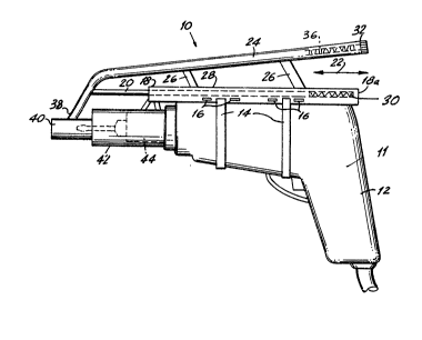
Figure 1 is a side elevational view of the invention and
associated driving tool at rest position;

Figure 2 iB a enlarged cross sectional view of the front
portion of the invention corresponding to the position in
Figure 1; and
:;
Figure 3 is an enlarged cross sectional view of the
front portion of a modification showing an adjustment spring
lo~ded ring and a knife for cutting the tape between the
screws with the driving tool starting its driving position.

,,

DETAILED DESCRIPTION OF THE PREFERRED EMBODIMENTS

Referring now to Figures 1, the automatic screw feed
tool of the present invention is shown generally at 10 mounted
to a conventional drill 12. The automatic screw feed tool 10
~: is mounted to the drill 12 by straps 14 that pass through
slots 16 in the stationary tube 18. A slide shaft 20 is
movable within the stationary tube 18 in direction of arrows
-~ : 20 22. A feed tube 24 is attached to the slide shaft 20 and

~,~
~ -3-

'''~ , ~

131~ 9~7


moves therewith. Supports 26 riding in a slot 28 further
support the feed tube 24.
The stationary tube 18 is closed at a one end 18a and
biases the slide shaft 20 with a spring 30. The feed tube 24
is closed at a one end 32 by a threaded cap 34 which is
removable to load screws 36. The other end 38 of the feed
tube 24 is connected to a sleeve 40 which is movable in a
stationary sleeve 42 which mounts over chuck 44 of the dxill
12.
The feeding arrangement is shown in greater detail in
Figure 2. The screws 36 are attached to a tape 46 and ride in
the interior of the feed tube 24. A spring 48 biases the
slide sleeve 40 in the extended position.
The screw 36 are fed via the tape 46 which is inside the
feed tube 24. the tape 46 with the screws 36 mounted therein
is inserted into the feed tube 24 by removing the threaded cap
~34~ The feed tube 24 is guided for longitudinal movement by --
~ ,,
the ~tationary tube 18 mounted on the drill 12. The
stationary tube 18 may be adjusted longitudinally relative to
the drill 12 by means of the slots 16 holding the straps 14.
In operation, the tool 10 is pressed against a working
;~ surface which forces the slide sleeve 40 to move inward of the
~tationary sleeve 42 against the bia~ing action of the spring
48 whereby the driver 47 is forced to engage the lead screw 36
' and drive it forward against the work surface. the driving
i forward action severs the lead screw 36 from the tape 46 and
:,
the screw 36 is then driven into the work surface. relieving
' ~

~ -4-

;~ , , , - , .

~ 13il9~7


the pressure of the tool 10 from the work surface causes
retraction of the driver 47 and permits the next screw 36 to
descend into the barrel of the slide sleeve 40.
An alternate embodiment is shown in Figure 3, where a
spring loaded knife 50 is forced inward to cut the tape 46 as
the driver 47 engages the lead screw 36 when the tool 10 is
pressed against the work surface. Additionally, an adjustment
ring 52 can be moved longitudinally in a slot 54 to change the
spring pressure of the spring 48, against the slide sleeve 40.
While certain novel features of this invention have been
shown and described and are pointed out in the annexed claims,
it will be understood that various omissions, substitutions
and changes in the forms and details of the device illustrated
and in its operation can be made by those skilled in the art
without departing from the spirit of the invention.

:


:, .


,,

f,
!~:
I f
.
~i" ~ :
f, ~ ~

~ 5-

I;
. I
1 .

Dessin représentatif
Une figure unique qui représente un dessin illustrant l'invention.
États administratifs

Pour une meilleure compréhension de l'état de la demande ou brevet qui figure sur cette page, la rubrique Mise en garde , et les descriptions de Brevet , États administratifs , Taxes périodiques et Historique des paiements devraient être consultées.

États administratifs

Titre Date
Date de délivrance prévu 1992-12-29
(22) Dépôt 1987-05-08
(45) Délivré 1992-12-29
Réputé périmé 1995-06-29

Historique d'abandonnement

Il n'y a pas d'historique d'abandonnement

Historique des paiements

Type de taxes Anniversaire Échéance Montant payé Date payée
Le dépôt d'une demande de brevet 0,00 $ 1987-05-08
Titulaires au dossier

Les titulaires actuels et antérieures au dossier sont affichés en ordre alphabétique.

Titulaires actuels au dossier
GOULD, FREDERICK H., JR.
SPECTOR, GEORGE
Titulaires antérieures au dossier
S.O.
Les propriétaires antérieurs qui ne figurent pas dans la liste des « Propriétaires au dossier » apparaîtront dans d'autres documents au dossier.
Documents

Pour visionner les fichiers sélectionnés, entrer le code reCAPTCHA :


Pour visualiser une image, cliquer sur un lien dans la colonne description du document. Pour télécharger l'image (les images), cliquer l'une ou plusieurs cases à cocher dans la première colonne et ensuite cliquer sur le bouton "Télécharger sélection en format PDF (archive Zip)" ou le bouton "Télécharger sélection (en un fichier PDF fusionné)".

Liste des documents de brevet publiés et non publiés sur la BDBC .

Si vous avez des difficultés à accéder au contenu, veuillez communiquer avec le Centre de services à la clientèle au 1-866-997-1936, ou envoyer un courriel au Centre de service à la clientèle de l'OPIC.


Description du
Document 
Date
(yyyy-mm-dd) 
Nombre de pages   Taille de l'image (Ko) 
Dessins 1993-11-09 1 37
Revendications 1993-11-09 3 90
Abrégé 1993-11-09 1 19
Page couverture 1993-11-09 1 13
Description 1993-11-09 5 146
Dessins représentatifs 2000-08-08 1 11