Note: Descriptions are shown in the official language in which they were submitted.
-- 2 1 32 79 ~ 7 21757-144
The present invention relates to a screening apparatus that
comprises at least two frame systems that can move relative to
each other, with grate bars that are associated with each system,
said grate bars alternating with each other by pairs, and being
connected by flexible screen elements that are secured to them,
which bridge the gap between said grate bars, and which are
tightened and slackened by means of a relative movement of the two
systems, this movement being brought about by an eccentric shaft
that is supported exclusively on the two systems and rotated by a
driving system.
Such a screening apparatus is described in German patent
specification No. l,206,372 issued December 9, 1965. In this, the
eccentric shaft is arranged halfway along the length of the screen
and the two systems are stabilized relative to each other by means
of springs. However, this known system does not satisfy the
demands imposed on it.
German patent application 32 14 943 laid-open October 27,
1983 describes a vibrating screen in which a box that incorporates
at least one screen base and which is supported elastically at its
ends is connected in the area of one of its centre points of
vibration to a vibration generator in the form of a shaft that is
arranged on the centre plane of the box and fitted with an
unbalanced weight.
An irregular field of vibration is thereby generated
transversely and longitudinally, and this brings about an
intensive loosening of the layer of material that is to be
. . , . , : ,., . : -
.. . . ~ . .
1327957
21757-144
screened. ~owever, such a construction cannot be transferred to
the screening apparatus described in the lntroduction hereto,
which incorporates two frames that oscillate relative to each
other, and the grate bars of which are connected to each other
_, ,
by means of flexible screening elements.
It is the task of the present invention to create a
screening apparatus that is of simple construction, inexpensive
to operate, and which has a prolonged service life. Above all,
however, such an apparatus must deliver good screening
performance. According to the present invention, this is
achieved with a screening apparatus of the type described in the
introduction hereto in that the eccentric shaft is arranged at
one end of the two systems, these belng connected at the other
end, or at a distance from this, by elements that ensure an
relative essentially linear movement of the two systems, such as
connecting rods, rubber blocks, or the llke.
If the eccentric shaft ls arranged at the end where the
material to be screened is introduced, the connecting rods or rod
llke connect ensures that lnitially the systems make circular
vibratory movements that gradually assume the form of ellipses
and in the area of the connecting rods assume a flat, circular,
or linear form. In the construction according to the present
lnvention, the desired reduction of the vibratory effect is
achleved without the need for any further measures. This makes
it possible to avold using exce~s driving energy, BO that a
higher degree of operating ef~iciency i~ achieved.
:
.....
-~ 1327957
21757-144
If the connecting rods or the like are moved closer to the
eccentric shaft, the frame systems describe elliptical vibrations
at the output end, which may be desirable for certain materials
that are to be screened.
It is particularly favourable if the connecting rods or the
like are arranged in the viainity of the pole of acceleration of
the vibratory system. In most instances, the distance between
the eccentric shaft and the connecting rods or the like can
amount to aproximately 60 to 80% of the length of the screen.
The ob;ect of the present invention is described in greater
detail below on the basis of an embodiment shown in the drawings
appended hereto. These drawings ehow the following:
Flgure 1: A side view, in partial cro~-section, o~ the screening
apparatus according to the present invention.
Figure 2: A cross-section.
Figure 3: A cross-section on the line III~III in figure 1.
Figure 4: A body that is acted on by an eccentric force.
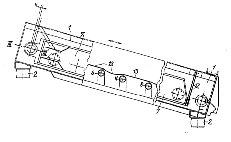
The screening apparatus incorporates a first screen system 1
that is ~upported through spring mountings 2 on a base or machine
frame (not shown herein). An eccentric shaft 3 is supported by
means of the bearings 4 within the frame system 1 and the
eccentrio 5 of this shaft 3 is supported in the bearings 6. As
is shown in figure 2, the frame system 7 is connected to the
grate bars ~ that pass through an opening 9 in the frame system
1 and are sarewed to a cross pieae of the frame 7. ~he opening 9
is closed off by a disk 10 that moves with the system 7.
.: .
.
1327957
21757-144
A~ can be seen from the lower part of figure 2, the frame 1
is bolted up with the grate bars 11, the grizzly bars 8
alternating with the grate bars 11.
At the output end, the two systems 1 and 7 are connected to
each other by means of the spring connecting rods 12. Because of
the oscillation of the two systems relative to each other,
generated by the eccentric shaft, the screen elements 13 that lie
between the grate bars 8 and 11 are alternately tightened and
slackened. The mutual, relative movement in the longitudinal
direction of the screen ele~ents 13 amounts to 2e, e standing for
the amount of eccentricity of the shaft 3.
BecauRe of the arrangement of a weight 14 on the eccentric
shaft 3, the amount of the vibratory movement of the system 1 in
the area of the eccentrlc shaft can be influenced positively.
Thus, for example, it can be arranged that the system vibrates
almost parallel to the surface of the screen, the amplitude
sufficing to ensure that the system 1 is self-cleaning.
The invention can undergo a further refinement, the physical
.
ba~is of whlch is explained in con~unction with figure 4.
Figure 4 shows a body K, the centre of gravity of which is
at PO. The force F acts at a point P~, with the result that a
tangential acceleration at and an angular acceleration a act
about the point PO.
The following calculations for the two accelerations at a
mass point P1 result:
,
. .
',;", ' ~ ~ '
~ :`
3279~7
a = a~r = M/~o M = F ~ s
a = ~ 8 r
at = F/m
wherein
r = distance of the mass point P1 from the centre of
gravity PO
M = the turning moment about the centre of gravity PQ
generated by the force F
s = the distance of the force F from the centre of gravity
Po
JO = the mass moment of inertia of the body K relative to
the centre of gravity PO
m = the mass of the budy K
The tangential acceleration at is of e~ual size and
directlon for all mass points of the body K.
The normal acceleration of the mass points increases ~ith
the distance from the centre of gravity PO and is perpendicular
to the line that connects the centre of gravity PO and the mass
point. For the mass point6 that are situated in a plane E that
is perpendicular to the force F and passes through the centre of
gravity PO, it is parallel to the tangential acceleration at.
The ~ormal acceleration is similarly oriented to the left of the
centre o~ gravity PO, and to the right thereof it is opposite to
the tangential acceleration.
Thus, on the plane E there is à point at which the
tangential acceleration and normal acceleration cancel each other
.' ~. ' ' ::
1~2'~â7
out. The pole of acceleration PB lies at thi~ point. Its
distance from the centre of gravity PO is X:
E~ X = F/m
X = ~0
ms
If an extended body of con6tant cross-section and length l
is involved, then
JO = m 12
12
If the distance of the force F from the centre of gravity PO
S = 1/2, then
X z l/6
If the connecting rods 12 or the like are arranged in the
area of the pole of acceleration, then restoring forces that have
a damping action of the drive are eliminated, whiah means that
less motive power is required. The system tends to accelerate
the material that is to be screened from the input end of the
screen to the pole of acceleration. From the pole of
acceleration to the end of the screen there is an increasing
deceleration of the material to be screened, ~o that there is a
longer period on the screen for screening out extreme particle
sizes and thus improved screening in thls range of particle
~ize~.
The mass of the material to be screened that is on the
screen can be taken lnto account when establishing the pole of
~ ' , '. . ~
13279~7
acceleration, in that the mass of the material to be screened is
factored into the calculation of the moment of mass inertia about
the common centre of gravity.
- ~ -
..
, . .
-
.
.
-, .: