Sélection de la langue

Search

Sommaire du brevet 1327957 

Énoncé de désistement de responsabilité concernant l'information provenant de tiers

Une partie des informations de ce site Web a été fournie par des sources externes. Le gouvernement du Canada n'assume aucune responsabilité concernant la précision, l'actualité ou la fiabilité des informations fournies par les sources externes. Les utilisateurs qui désirent employer cette information devraient consulter directement la source des informations. Le contenu fourni par les sources externes n'est pas assujetti aux exigences sur les langues officielles, la protection des renseignements personnels et l'accessibilité.

Disponibilité de l'Abrégé et des Revendications

L'apparition de différences dans le texte et l'image des Revendications et de l'Abrégé dépend du moment auquel le document est publié. Les textes des Revendications et de l'Abrégé sont affichés :

  • lorsque la demande peut être examinée par le public;
  • lorsque le brevet est émis (délivrance).
(12) Brevet: (11) CA 1327957
(21) Numéro de la demande: 1327957
(54) Titre français: CRIBLE
(54) Titre anglais: SCREENING APPARATUS
Statut: Périmé et au-delà du délai pour l’annulation
Données bibliographiques
(51) Classification internationale des brevets (CIB):
  • B07B 01/28 (2006.01)
  • B07B 01/42 (2006.01)
  • B07B 01/46 (2006.01)
  • B07B 01/48 (2006.01)
(72) Inventeurs :
  • AHORNER, LEANDER (Autriche)
(73) Titulaires :
  • IFE INDUSTRIE-EINRICHTUNGEN FERTIGUNGS-AKTIENGESELLSCHAFT
(71) Demandeurs :
  • IFE INDUSTRIE-EINRICHTUNGEN FERTIGUNGS-AKTIENGESELLSCHAFT (Autriche)
(74) Agent: SMART & BIGGAR LP
(74) Co-agent:
(45) Délivré: 1994-03-22
(22) Date de dépôt: 1989-09-05
Licence disponible: S.O.
Cédé au domaine public: S.O.
(25) Langue des documents déposés: Anglais

Traité de coopération en matière de brevets (PCT): Non

(30) Données de priorité de la demande:
Numéro de la demande Pays / territoire Date
A 2178/88 (Autriche) 1988-09-05

Abrégés

Abrégé anglais


Abstract
The present invention relates to a screening apparatus that
comprises at least two frame systems that can move relative to
each other, with grate bars that are associated with each
system, said grate bars alternating with each other by pairs
and being connected by flexible screen elements that are secured
to them, that bridge the gap between said grate bars, and which
are tightened and slackened by means of a relative movement of
the two systems, this movement being brought about by an
eccentric shaft that is supported exclusively on the two systems
and rotated by a driving system. According to the present
invention, this system has been improved in that the eccentric
shaft is arranged at one end of the two systems, and
these are connected to each other at the other end or at a
distance from this by means of an element, such as a
connecting rod or rubber blocks,that ensures an essentially
linear relative movement of the two systems towards each other.
It is preferred that the cited distance corresponds to that
distance that separates the pole of acceleration of the
vibratory systems from the eccentric shaft.

Revendications

Note : Les revendications sont présentées dans la langue officielle dans laquelle elles ont été soumises.


- 9 -
THE EMBODIMENTS OF THE INVENTION IN WHICH AN EXCLUSIVE
PROPERTY OR PRIVILEGE IS CLAIMED ARE DEFINED AS FOLLOWS:
1. A screening apparatus that comprises at least two
frame systems that can move relative to each other, with grate
bars that are associated with each system, said grate bars alter-
nating with each other by pairs and being connected by flexible
screen elements that are secured to them, that bridge the gap
between said grate bars, and which are tightened and slackened by
means of a relative movement of the two systems, this movement
being brought about by an eccentric shaft that is supported ex-
clusively on the two systems and rotated by a driving system,
characterized in that the eccentric shaft is arranged at one end of
the two systems, and these are connected to each other at the other
end or at a distance from this by means of an element, such as a
connecting rod or rubber blocks, that ensures an essentially
linear relative movement of the two systems towards each other.
2. A screening apparatus as defined in claim 1, where-
in the eccentric shaft is arranged at the input end for the
material that is to be screened.
3. A screening apparatus as defined in claim 1 or claim
2, wherein the eccentric shaft is fitted with a counter-weight.
4. A screening apparatus as defined in claim 1,
wherein the distance between the eccentric shaft and the element
that ensures an essentially linear movement of the two vibratory
systems towards each other, corresponds approximately to the
distance of the pole of acceleration of the systems from the
eccentric shaft.

- 10 -
5. A screening apparatus as defined in claim 4, where-
in the distance is 20 per cent smaller than the length of the
screen.

Description

Note : Les descriptions sont présentées dans la langue officielle dans laquelle elles ont été soumises.

-- 2 1 32 79 ~ 7 21757-144
The present invention relates to a screening apparatus that
comprises at least two frame systems that can move relative to
each other, with grate bars that are associated with each system,
said grate bars alternating with each other by pairs, and being
connected by flexible screen elements that are secured to them,
which bridge the gap between said grate bars, and which are
tightened and slackened by means of a relative movement of the two
systems, this movement being brought about by an eccentric shaft
that is supported exclusively on the two systems and rotated by a
driving system.
Such a screening apparatus is described in German patent
specification No. l,206,372 issued December 9, 1965. In this, the
eccentric shaft is arranged halfway along the length of the screen
and the two systems are stabilized relative to each other by means
of springs. However, this known system does not satisfy the
demands imposed on it.
German patent application 32 14 943 laid-open October 27,
1983 describes a vibrating screen in which a box that incorporates
at least one screen base and which is supported elastically at its
ends is connected in the area of one of its centre points of
vibration to a vibration generator in the form of a shaft that is
arranged on the centre plane of the box and fitted with an
unbalanced weight.
An irregular field of vibration is thereby generated
transversely and longitudinally, and this brings about an
intensive loosening of the layer of material that is to be
. . , . , : ,., . : -
.. . . ~ . .

1327957
21757-144
screened. ~owever, such a construction cannot be transferred to
the screening apparatus described in the lntroduction hereto,
which incorporates two frames that oscillate relative to each
other, and the grate bars of which are connected to each other
_, ,
by means of flexible screening elements.
It is the task of the present invention to create a
screening apparatus that is of simple construction, inexpensive
to operate, and which has a prolonged service life. Above all,
however, such an apparatus must deliver good screening
performance. According to the present invention, this is
achieved with a screening apparatus of the type described in the
introduction hereto in that the eccentric shaft is arranged at
one end of the two systems, these belng connected at the other
end, or at a distance from this, by elements that ensure an
relative essentially linear movement of the two systems, such as
connecting rods, rubber blocks, or the llke.
If the eccentric shaft ls arranged at the end where the
material to be screened is introduced, the connecting rods or rod
llke connect ensures that lnitially the systems make circular
vibratory movements that gradually assume the form of ellipses
and in the area of the connecting rods assume a flat, circular,
or linear form. In the construction according to the present
lnvention, the desired reduction of the vibratory effect is
achleved without the need for any further measures. This makes
it possible to avold using exce~s driving energy, BO that a
higher degree of operating ef~iciency i~ achieved.
:
.....

-~ 1327957
21757-144
If the connecting rods or the like are moved closer to the
eccentric shaft, the frame systems describe elliptical vibrations
at the output end, which may be desirable for certain materials
that are to be screened.
It is particularly favourable if the connecting rods or the
like are arranged in the viainity of the pole of acceleration of
the vibratory system. In most instances, the distance between
the eccentric shaft and the connecting rods or the like can
amount to aproximately 60 to 80% of the length of the screen.
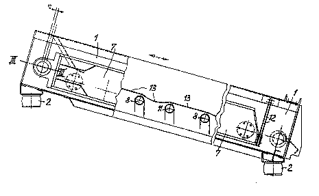
The ob;ect of the present invention is described in greater
detail below on the basis of an embodiment shown in the drawings
appended hereto. These drawings ehow the following:
Flgure 1: A side view, in partial cro~-section, o~ the screening
apparatus according to the present invention.
Figure 2: A cross-section.
Figure 3: A cross-section on the line III~III in figure 1.
Figure 4: A body that is acted on by an eccentric force.
The screening apparatus incorporates a first screen system 1
that is ~upported through spring mountings 2 on a base or machine
frame (not shown herein). An eccentric shaft 3 is supported by
means of the bearings 4 within the frame system 1 and the
eccentrio 5 of this shaft 3 is supported in the bearings 6. As
is shown in figure 2, the frame system 7 is connected to the
grate bars ~ that pass through an opening 9 in the frame system
1 and are sarewed to a cross pieae of the frame 7. ~he opening 9
is closed off by a disk 10 that moves with the system 7.
.: .
.

1327957
21757-144
A~ can be seen from the lower part of figure 2, the frame 1
is bolted up with the grate bars 11, the grizzly bars 8
alternating with the grate bars 11.
At the output end, the two systems 1 and 7 are connected to
each other by means of the spring connecting rods 12. Because of
the oscillation of the two systems relative to each other,
generated by the eccentric shaft, the screen elements 13 that lie
between the grate bars 8 and 11 are alternately tightened and
slackened. The mutual, relative movement in the longitudinal
direction of the screen ele~ents 13 amounts to 2e, e standing for
the amount of eccentricity of the shaft 3.
BecauRe of the arrangement of a weight 14 on the eccentric
shaft 3, the amount of the vibratory movement of the system 1 in
the area of the eccentrlc shaft can be influenced positively.
Thus, for example, it can be arranged that the system vibrates
almost parallel to the surface of the screen, the amplitude
sufficing to ensure that the system 1 is self-cleaning.
The invention can undergo a further refinement, the physical
.
ba~is of whlch is explained in con~unction with figure 4.
Figure 4 shows a body K, the centre of gravity of which is
at PO. The force F acts at a point P~, with the result that a
tangential acceleration at and an angular acceleration a act
about the point PO.
The following calculations for the two accelerations at a
mass point P1 result:
,
. .
',;", ' ~ ~ '

~ :`
3279~7
a = a~r = M/~o M = F ~ s
a = ~ 8 r
at = F/m
wherein
r = distance of the mass point P1 from the centre of
gravity PO
M = the turning moment about the centre of gravity PQ
generated by the force F
s = the distance of the force F from the centre of gravity
Po
JO = the mass moment of inertia of the body K relative to
the centre of gravity PO
m = the mass of the budy K
The tangential acceleration at is of e~ual size and
directlon for all mass points of the body K.
The normal acceleration of the mass points increases ~ith
the distance from the centre of gravity PO and is perpendicular
to the line that connects the centre of gravity PO and the mass
point. For the mass point6 that are situated in a plane E that
is perpendicular to the force F and passes through the centre of
gravity PO, it is parallel to the tangential acceleration at.
The ~ormal acceleration is similarly oriented to the left of the
centre o~ gravity PO, and to the right thereof it is opposite to
the tangential acceleration.
Thus, on the plane E there is à point at which the
tangential acceleration and normal acceleration cancel each other
.' ~. ' ' ::

1~2'~â7
out. The pole of acceleration PB lies at thi~ point. Its
distance from the centre of gravity PO is X:
E~ X = F/m
X = ~0
ms
If an extended body of con6tant cross-section and length l
is involved, then
JO = m 12
12
If the distance of the force F from the centre of gravity PO
S = 1/2, then
X z l/6
If the connecting rods 12 or the like are arranged in the
area of the pole of acceleration, then restoring forces that have
a damping action of the drive are eliminated, whiah means that
less motive power is required. The system tends to accelerate
the material that is to be screened from the input end of the
screen to the pole of acceleration. From the pole of
acceleration to the end of the screen there is an increasing
deceleration of the material to be screened, ~o that there is a
longer period on the screen for screening out extreme particle
sizes and thus improved screening in thls range of particle
~ize~.
The mass of the material to be screened that is on the
screen can be taken lnto account when establishing the pole of
~ ' , '. . ~

13279~7
acceleration, in that the mass of the material to be screened is
factored into the calculation of the moment of mass inertia about
the common centre of gravity.
- ~ -
..
, . .
-
.
.
-, .:

Dessin représentatif
Une figure unique qui représente un dessin illustrant l'invention.
États administratifs

2024-08-01 : Dans le cadre de la transition vers les Brevets de nouvelle génération (BNG), la base de données sur les brevets canadiens (BDBC) contient désormais un Historique d'événement plus détaillé, qui reproduit le Journal des événements de notre nouvelle solution interne.

Veuillez noter que les événements débutant par « Inactive : » se réfèrent à des événements qui ne sont plus utilisés dans notre nouvelle solution interne.

Pour une meilleure compréhension de l'état de la demande ou brevet qui figure sur cette page, la rubrique Mise en garde , et les descriptions de Brevet , Historique d'événement , Taxes périodiques et Historique des paiements devraient être consultées.

Historique d'événement

Description Date
Inactive : Renversement de l'état périmé 2012-12-05
Le délai pour l'annulation est expiré 2011-03-22
Lettre envoyée 2010-03-22
Inactive : CIB de MCD 2006-03-11
Accordé par délivrance 1994-03-22

Historique d'abandonnement

Il n'y a pas d'historique d'abandonnement

Titulaires au dossier

Les titulaires actuels et antérieures au dossier sont affichés en ordre alphabétique.

Titulaires actuels au dossier
IFE INDUSTRIE-EINRICHTUNGEN FERTIGUNGS-AKTIENGESELLSCHAFT
Titulaires antérieures au dossier
LEANDER AHORNER
Les propriétaires antérieurs qui ne figurent pas dans la liste des « Propriétaires au dossier » apparaîtront dans d'autres documents au dossier.
Documents

Pour visionner les fichiers sélectionnés, entrer le code reCAPTCHA :


Pour visualiser une image, cliquer sur un lien dans la colonne description du document. Pour télécharger l'image (les images), cliquer l'une ou plusieurs cases à cocher dans la première colonne et ensuite cliquer sur le bouton "Télécharger sélection en format PDF (archive Zip)" ou le bouton "Télécharger sélection (en un fichier PDF fusionné)".

Liste des documents de brevet publiés et non publiés sur la BDBC .

Si vous avez des difficultés à accéder au contenu, veuillez communiquer avec le Centre de services à la clientèle au 1-866-997-1936, ou envoyer un courriel au Centre de service à la clientèle de l'OPIC.


Description du
Document 
Date
(aaaa-mm-jj) 
Nombre de pages   Taille de l'image (Ko) 
Abrégé 1994-07-21 1 30
Revendications 1994-07-21 2 48
Dessins 1994-07-21 1 41
Description 1994-07-21 7 198
Dessin représentatif 2000-08-07 1 14
Avis concernant la taxe de maintien 2010-05-02 1 170
Courtoisie - Lettre du bureau 1989-12-04 1 38
Correspondance reliée au PCT 1989-10-03 1 19
Correspondance reliée au PCT 1989-12-12 1 37
Correspondance reliée au PCT 1993-12-19 1 23
Correspondance de la poursuite 1992-08-11 2 51
Correspondance de la poursuite 1992-06-23 1 37
Demande de l'examinateur 1992-03-16 1 72
Taxes 2003-01-15 1 37
Taxes 2003-12-22 1 37
Taxes 2002-03-06 1 36
Taxes 2004-10-31 1 33
Taxes 1997-02-09 1 52
Taxes 1996-02-12 1 46