Language selection

Search

Patent 2018810 Summary

Third-party information liability

Some of the information on this Web page has been provided by external sources. The Government of Canada is not responsible for the accuracy, reliability or currency of the information supplied by external sources. Users wishing to rely upon this information should consult directly with the source of the information. Content provided by external sources is not subject to official languages, privacy and accessibility requirements.

Claims and Abstract availability

Any discrepancies in the text and image of the Claims and Abstract are due to differing posting times. Text of the Claims and Abstract are posted:

  • At the time the application is open to public inspection;
  • At the time of issue of the patent (grant).
(12) Patent: (11) CA 2018810
(54) English Title: HOSE ROTATION RESTRAINER
(54) French Title: DISPOSITIF DE BLOCAGE D'UN TUYAU SOUPLE
Status: Deemed expired
Bibliographic Data
(52) Canadian Patent Classification (CPC):
  • 189/61
(51) International Patent Classification (IPC):
  • F16L 11/00 (2006.01)
  • B67D 7/04 (2010.01)
  • F16L 3/12 (2006.01)
(72) Inventors :
  • STANLEY, JOHN HOWARD (United States of America)
(73) Owners :
  • THE GOODYEAR TIRE & RUBBER COMPANY (United States of America)
(71) Applicants :
(74) Agent: SIM & MCBURNEY
(74) Associate agent:
(45) Issued: 1997-12-02
(22) Filed Date: 1990-06-12
(41) Open to Public Inspection: 1991-04-13
Examination requested: 1996-11-21
Availability of licence: N/A
(25) Language of filing: English

Patent Cooperation Treaty (PCT): No

(30) Application Priority Data:
Application No. Country/Territory Date
420,510 United States of America 1989-10-13

Abstracts

English Abstract


A hose rotation restrainer which attaches to the
inner product hose of a coaxial vapor recovery hose
assembly along with the inlet end of a suction tube in
the vapor passageway between the inner product hose and
the outer hose to prevent rotation of the product hose
in order to maintain the end of the suction tube at a
low point in the catenary of the hose assembly for
removing liquid accumulations.


French Abstract

Cette invention concerne un limiteur de rotation de flexible à monter sur le flexible intérieur de distribution d'un tuyau coaxial à récupération de vapeurs et servant en même temps à fixer au flexible intérieur l'extrémité libre d'un tube d'aspiration logé dans le ssage de récupération de vapeurs. L'objet de l'invention sert à empêcher la rotation du flexible intérieur de telle sorte que le tube d'aspiration de condensat se trouve toujours au point bas du tuyau coaxial.

Claims

Note: Claims are shown in the official language in which they were submitted.


-6-


I CLAIM:

1. In a coaxial vapor recovery hose assembly
having an inner product hose having an outer radius and
an outer diameter, an outer hose coaxially surrounding
said product hose and defining therewith an annular
vapor passageway therebetween and a suction tube which
extends to a low point of the catenary of the hose
assembly while in use, a cradle-shaped hose rotation
restrainer, attached to said product hose at said low
point and comprising a pair of arcuate, parallel
members connected at each end thereof by semicircular
loops having a radius equal to the outer radius of the
product hose, said members being spaced apart a
distance equal to the outer diameter of the product
hose.

2. The restrainer according to claim 1 wherein
said members and said loops are formed from a
continuous piece of material.

3. The restrainer according to claim 1 wherein it
is formed of a material which is rigid enough to retain
the arcuate shape of the restrainer when no tension is
exerted on the hose assembly, yet flexible enough to
straighten out when tension is exerted on the hose
assembly.

4. A coaxial vapor recovery hose assembly
comprising an inner product hose having an outer radius


-7-


and an outer diameter; an outer hose coaxially
surrounding said product hose and defining therewith an
annular vapor passageway therebetween; a suction tube
located within said passageway and connected at one end
to a suction means, the other end thereof being located
at a low point of the catenary of said hose assembly
while in use; a cradle-shaped hose rotation restrainer
attached to said product hose at said low point and
comprising a pair of arcuate, parallel members
connected at each end thereof by a semicircular loop
having a radius equal to said product hose radius, said
members being spaced apart a distance equal to said
product hose diameter; and means for attaching said
restrainer and said suction tube to said low point of
the product hose.

Description

Note: Descriptions are shown in the official language in which they were submitted.


~ HOSE ROTATION RESTRAINER ~ ~ 9

Field of the Invention
This invention relates to coaxiàl vapor recovery
hose assemblies. More particularly, it relates to a
hose rotation restrainer.

Background of the Invention
The use of coaxial vapor recovery hose
assemblies for delivering fuel from a pump stand to a
valved nozzle for refueling motor vehicles has been
known for many years. More recently, such vapor
recovery hose assemblies have included a means for
sucking any accumulated liquid from a low point in
the catenary of the hose assembly resulting from
splashback or a collection of condensed vapors. Such
means for sucking the liquid generally includes a
Venturi pump which operates through the passage of
the fuel product through the Venturl to create a
suction at an orifice connected to the Venturi
throat. A suction tube is connected to the orifice
with the other end of the suction tube located at the
low point in the catenary of the hose assembly in the
vapor passageway between the product hose and the
outer hose and is generally attached to the product
hose on the bottom in order to be located where any
liquid would accumulate.
In order to assure that the suction tube remains
at such a low point while attached to the product
hose, it is necessary to assure that the product hose
does not rotate within the vapor passageway. It is
therefore an object of an aspect of the present
invention to provide a hose rotation restrainer
which, when attached to the inner product hose of a
coaxial vapor recovery hose assembly, will prevent
the rotation of the inner product hose. It is an

2~8 ~n
object of an aspect of the present invention to
provide an assembly utilizing the hose rotation
restrainer which also encompasses attaahing the .
suction tube to the low point in the catenary of the
hose while the hose is being used in the refueling
operation.

Summary of the Invention
In accordance with the practice of the present
invention, there is provided in a coaxial vapor
recovery hose assembly having an inner product hose
having an outer radius and an outer diameter, an
outer hose coaxially surrounding the product hose and
defining therewith an annular vapor passageway
therebetween and a suction tube which extends to a
low point of the catenary of the hose assembly while
in use, a cradle-shaped hose rotation restrainer
attached to the product hose at the low point and
comprising a pair of arcuate, parallel members having
inwardly extending loops at each end of the members
and connected at each end thereof by a semicircular
loop having a radius equal to the outer radius of the
product hose, the members being spaced apart a
distance equal to the outer diameter of the product
hose. There is also provided a coaxial vapor
recovery hose assembly comprising an inner product
hose; an outer hose coaxially surrounding the product
hose to define therewith an annular vapor passageway
therebetween; a suction tube located within the
passageway and connected at one end to a suction
means, the other end thereof being located at a low
point of the catenary of the hose assembly while in
use; a cradle-shaped hose rotation restrainer
attached to the product hose at the low point; and
means for attaching the restrainer and the suction
tube to the low point of the product hose.

S~

Z018810


Brief Description of the Drawings
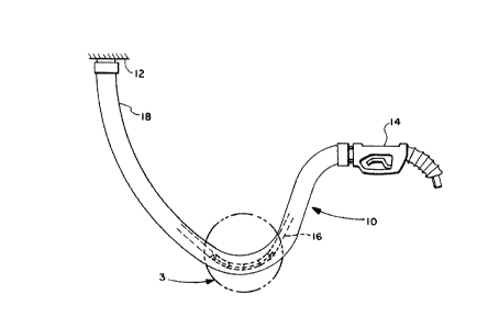
Fig. 1 illustrates a typical coaxial vapor recovery
hose assembly, showing in phantom the inner product
hose having attached thereto the hose rotation
restrainer of the present invention.
Fig. 2 is a perspective view of the hose rotation
restrainer of the instant invention.
Fig. 3 is an exploded view, partly in section, of
the low point in the catenary of the hose assembly of
the encircled area denoted by numeral 3 in Fig. 1.

Detailed Description of the Invention
Fig. 1 illustrates a coaxial hose assembly denoted
generally as 10 which is connected between a pump stand
12 and a product dispensing nozzle 14. The hose
assembly comprises an inner product hose 16, having an
outer radius and an outer diameter. Coaxially
surrounding the product hose 16 is the outer hose 18
which, with the product hose 16, defines an annular
vapor passageway 20 therebetween. In operation, the
inner product hose 16 conducts the fuel from the pump
stand 12 through the product nozzle 14 into a motor
vehicle fuel tank. Vapors being displaced from the
motor vehicle fuel tank are returned through the
dispensing nozzle 14 through the vapor passageway 20
back to the pump stand 12. Should the vapors condense
or should a splashback from the vehicle fuel tank
occur, the liquid would accumulate in the low point of
the catenary 3 of the hose assembly. In order to keep
the annular vapor passageway 20 clear of liquid
accumulation, it is necessary to suck the liquid out of
the low point in the catenary 3 by means of a suction
tube 26 whose inlet end is located at the low point of
the catenary 3 and whose other end is connected to a

Z018810


suction means (not shown). In order to prevent the
rotation of the inner product hose 16 and to retain the
inlet end to the suction tube 26 on the bottom of the
product hose 16, there is provided a hose rotation
restrainer 22 which is attached to the inner product
hose 16 by attaching means 24, preferably in the form
of what is commonly known as cable ties.
The cradle-shaped hose rotation restrainer
comprises a pair of arcuate, parallel members 21 having
inwardly extending loops 23 at each end of the members
and connected at each end thereof by a semicircular
loop 22a,22b having a radius equal to the outer radius
of the product hose wherein the members are spaced
apart a distance equal to the outer diameter of the
product hose. While it is preferred that the hose
rotation restrainer be formed of one continuous piece
of material, as illustrated, for simplicity of
manufacture, it can be appreciated that the restrainer
can be formed from a plurality of individual
components.
It is preferred that the hose rotation restrainer
be made of metallic wire such as piano wire or spring
wire which is bent to the shape illustrated in Fig. 2,
but it is also contemplated that the hose rotation
restrainer could be formed in a molding operation using
a material such as a thermoplastic. The only criteria
for the material is that it be sufficiently rigid to
retain the arcuate shape when no tension is exerted on
the hose assembly, yet be flexible enough to straighten
out when a tension is exerted on the hose assembly.
In operation, the hose rotation restrainer 22 and
the suction tube 26 are attached to the bottom of the
product hose 16 by attaching means 24 such that the
suction tube 26 is located on the bottom of the product

Z018810

--5--
hose 16 at the low point in the catenary 3 of the
coaxial vapor recovery hose assembly. This allows the
suction means to draw any accumulated liquid out of the
vapor passageway 20 in order to allow the vapors to
return from the vehicle fuel tank to the pump stand.
While certain representative embodiments have been
shown for the purpose of illustrating the present
invention, it will be apparent to those skilled in the
art that various changes and modifications may be made
therein without departing from the spirit or scope of
the invention.

Representative Drawing
A single figure which represents the drawing illustrating the invention.
Administrative Status

For a clearer understanding of the status of the application/patent presented on this page, the site Disclaimer , as well as the definitions for Patent , Administrative Status , Maintenance Fee  and Payment History  should be consulted.

Administrative Status

Title Date
Forecasted Issue Date 1997-12-02
(22) Filed 1990-06-12
(41) Open to Public Inspection 1991-04-13
Examination Requested 1996-11-21
(45) Issued 1997-12-02
Deemed Expired 2001-06-12

Abandonment History

There is no abandonment history.

Payment History

Fee Type Anniversary Year Due Date Amount Paid Paid Date
Application Fee $0.00 1990-06-12
Registration of a document - section 124 $0.00 1990-11-14
Maintenance Fee - Application - New Act 2 1992-06-12 $100.00 1992-03-27
Maintenance Fee - Application - New Act 3 1993-06-14 $100.00 1993-03-29
Maintenance Fee - Application - New Act 4 1994-06-13 $100.00 1994-03-24
Maintenance Fee - Application - New Act 5 1995-06-12 $150.00 1995-03-23
Maintenance Fee - Application - New Act 6 1996-06-12 $150.00 1996-03-22
Maintenance Fee - Application - New Act 7 1997-06-12 $150.00 1997-03-27
Final Fee $300.00 1997-08-05
Maintenance Fee - Patent - New Act 8 1998-06-12 $150.00 1998-05-04
Maintenance Fee - Patent - New Act 9 1999-06-14 $150.00 1999-05-03
Owners on Record

Note: Records showing the ownership history in alphabetical order.

Current Owners on Record
THE GOODYEAR TIRE & RUBBER COMPANY
Past Owners on Record
STANLEY, JOHN HOWARD
Past Owners that do not appear in the "Owners on Record" listing will appear in other documentation within the application.
Documents

To view selected files, please enter reCAPTCHA code :


To view images, click a link in the Document Description column. To download the documents, select one or more checkboxes in the first column and then click the "Download Selected in PDF format (Zip Archive)" or the "Download Selected as Single PDF" button.

List of published and non-published patent-specific documents on the CPD .

If you have any difficulty accessing content, you can call the Client Service Centre at 1-866-997-1936 or send them an e-mail at CIPO Client Service Centre.


Document
Description 
Date
(yyyy-mm-dd) 
Number of pages   Size of Image (KB) 
Cover Page 1997-11-24 1 33
Cover Page 1993-11-20 1 13
Abstract 1993-11-20 1 13
Drawings 1993-11-20 1 25
Description 1993-11-20 2 48
Description 1993-11-20 5 174
Description 1997-02-18 5 185
Claims 1997-12-01 2 48
Description 1998-08-20 5 185
Representative Drawing 1997-11-24 1 5
PCT Correspondence 1996-11-21 1 51
PCT Correspondence 1997-08-05 1 59
Prosecution Correspondence 1996-12-11 3 90
Fees 1997-03-27 1 61
Fees 1996-03-22 1 55
Fees 1995-03-23 1 61
Fees 1994-03-24 1 45
Fees 1993-03-29 1 40
Fees 1992-03-27 1 56