Sélection de la langue

Search

Sommaire du brevet 2018810 

Énoncé de désistement de responsabilité concernant l'information provenant de tiers

Une partie des informations de ce site Web a été fournie par des sources externes. Le gouvernement du Canada n'assume aucune responsabilité concernant la précision, l'actualité ou la fiabilité des informations fournies par les sources externes. Les utilisateurs qui désirent employer cette information devraient consulter directement la source des informations. Le contenu fourni par les sources externes n'est pas assujetti aux exigences sur les langues officielles, la protection des renseignements personnels et l'accessibilité.

Disponibilité de l'Abrégé et des Revendications

L'apparition de différences dans le texte et l'image des Revendications et de l'Abrégé dépend du moment auquel le document est publié. Les textes des Revendications et de l'Abrégé sont affichés :

  • lorsque la demande peut être examinée par le public;
  • lorsque le brevet est émis (délivrance).
(12) Brevet: (11) CA 2018810
(54) Titre français: DISPOSITIF DE BLOCAGE D'UN TUYAU SOUPLE
(54) Titre anglais: HOSE ROTATION RESTRAINER
Statut: Périmé et au-delà du délai pour l’annulation
Données bibliographiques
(51) Classification internationale des brevets (CIB):
  • F16L 11/00 (2006.01)
  • B67D 7/04 (2010.01)
  • F16L 3/12 (2006.01)
(72) Inventeurs :
  • STANLEY, JOHN HOWARD (Etats-Unis d'Amérique)
(73) Titulaires :
  • THE GOODYEAR TIRE & RUBBER COMPANY
(71) Demandeurs :
  • THE GOODYEAR TIRE & RUBBER COMPANY (Etats-Unis d'Amérique)
(74) Agent: MARKS & CLERK
(74) Co-agent:
(45) Délivré: 1997-12-02
(22) Date de dépôt: 1990-06-12
(41) Mise à la disponibilité du public: 1991-04-13
Requête d'examen: 1996-11-21
Licence disponible: S.O.
Cédé au domaine public: S.O.
(25) Langue des documents déposés: Anglais

Traité de coopération en matière de brevets (PCT): Non

(30) Données de priorité de la demande:
Numéro de la demande Pays / territoire Date
420,510 (Etats-Unis d'Amérique) 1989-10-13

Abrégés

Abrégé français

Cette invention concerne un limiteur de rotation de flexible à monter sur le flexible intérieur de distribution d'un tuyau coaxial à récupération de vapeurs et servant en même temps à fixer au flexible intérieur l'extrémité libre d'un tube d'aspiration logé dans le ssage de récupération de vapeurs. L'objet de l'invention sert à empêcher la rotation du flexible intérieur de telle sorte que le tube d'aspiration de condensat se trouve toujours au point bas du tuyau coaxial.


Abrégé anglais


A hose rotation restrainer which attaches to the
inner product hose of a coaxial vapor recovery hose
assembly along with the inlet end of a suction tube in
the vapor passageway between the inner product hose and
the outer hose to prevent rotation of the product hose
in order to maintain the end of the suction tube at a
low point in the catenary of the hose assembly for
removing liquid accumulations.

Revendications

Note : Les revendications sont présentées dans la langue officielle dans laquelle elles ont été soumises.


-6-
I CLAIM:
1. In a coaxial vapor recovery hose assembly
having an inner product hose having an outer radius and
an outer diameter, an outer hose coaxially surrounding
said product hose and defining therewith an annular
vapor passageway therebetween and a suction tube which
extends to a low point of the catenary of the hose
assembly while in use, a cradle-shaped hose rotation
restrainer, attached to said product hose at said low
point and comprising a pair of arcuate, parallel
members connected at each end thereof by semicircular
loops having a radius equal to the outer radius of the
product hose, said members being spaced apart a
distance equal to the outer diameter of the product
hose.
2. The restrainer according to claim 1 wherein
said members and said loops are formed from a
continuous piece of material.
3. The restrainer according to claim 1 wherein it
is formed of a material which is rigid enough to retain
the arcuate shape of the restrainer when no tension is
exerted on the hose assembly, yet flexible enough to
straighten out when tension is exerted on the hose
assembly.
4. A coaxial vapor recovery hose assembly
comprising an inner product hose having an outer radius

-7-
and an outer diameter; an outer hose coaxially
surrounding said product hose and defining therewith an
annular vapor passageway therebetween; a suction tube
located within said passageway and connected at one end
to a suction means, the other end thereof being located
at a low point of the catenary of said hose assembly
while in use; a cradle-shaped hose rotation restrainer
attached to said product hose at said low point and
comprising a pair of arcuate, parallel members
connected at each end thereof by a semicircular loop
having a radius equal to said product hose radius, said
members being spaced apart a distance equal to said
product hose diameter; and means for attaching said
restrainer and said suction tube to said low point of
the product hose.

Description

Note : Les descriptions sont présentées dans la langue officielle dans laquelle elles ont été soumises.

~ HOSE ROTATION RESTRAINER ~ ~ 9
Field of the Invention
This invention relates to coaxiàl vapor recovery
hose assemblies. More particularly, it relates to a
hose rotation restrainer.
Background of the Invention
The use of coaxial vapor recovery hose
assemblies for delivering fuel from a pump stand to a
valved nozzle for refueling motor vehicles has been
known for many years. More recently, such vapor
recovery hose assemblies have included a means for
sucking any accumulated liquid from a low point in
the catenary of the hose assembly resulting from
splashback or a collection of condensed vapors. Such
means for sucking the liquid generally includes a
Venturi pump which operates through the passage of
the fuel product through the Venturl to create a
suction at an orifice connected to the Venturi
throat. A suction tube is connected to the orifice
with the other end of the suction tube located at the
low point in the catenary of the hose assembly in the
vapor passageway between the product hose and the
outer hose and is generally attached to the product
hose on the bottom in order to be located where any
liquid would accumulate.
In order to assure that the suction tube remains
at such a low point while attached to the product
hose, it is necessary to assure that the product hose
does not rotate within the vapor passageway. It is
therefore an object of an aspect of the present
invention to provide a hose rotation restrainer
which, when attached to the inner product hose of a
coaxial vapor recovery hose assembly, will prevent
the rotation of the inner product hose. It is an

2~8 ~n
object of an aspect of the present invention to
provide an assembly utilizing the hose rotation
restrainer which also encompasses attaahing the .
suction tube to the low point in the catenary of the
hose while the hose is being used in the refueling
operation.
Summary of the Invention
In accordance with the practice of the present
invention, there is provided in a coaxial vapor
recovery hose assembly having an inner product hose
having an outer radius and an outer diameter, an
outer hose coaxially surrounding the product hose and
defining therewith an annular vapor passageway
therebetween and a suction tube which extends to a
low point of the catenary of the hose assembly while
in use, a cradle-shaped hose rotation restrainer
attached to the product hose at the low point and
comprising a pair of arcuate, parallel members having
inwardly extending loops at each end of the members
and connected at each end thereof by a semicircular
loop having a radius equal to the outer radius of the
product hose, the members being spaced apart a
distance equal to the outer diameter of the product
hose. There is also provided a coaxial vapor
recovery hose assembly comprising an inner product
hose; an outer hose coaxially surrounding the product
hose to define therewith an annular vapor passageway
therebetween; a suction tube located within the
passageway and connected at one end to a suction
means, the other end thereof being located at a low
point of the catenary of the hose assembly while in
use; a cradle-shaped hose rotation restrainer
attached to the product hose at the low point; and
means for attaching the restrainer and the suction
tube to the low point of the product hose.
S~

Z018810
Brief Description of the Drawings
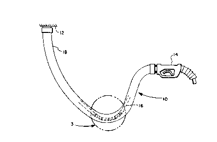
Fig. 1 illustrates a typical coaxial vapor recovery
hose assembly, showing in phantom the inner product
hose having attached thereto the hose rotation
restrainer of the present invention.
Fig. 2 is a perspective view of the hose rotation
restrainer of the instant invention.
Fig. 3 is an exploded view, partly in section, of
the low point in the catenary of the hose assembly of
the encircled area denoted by numeral 3 in Fig. 1.
Detailed Description of the Invention
Fig. 1 illustrates a coaxial hose assembly denoted
generally as 10 which is connected between a pump stand
12 and a product dispensing nozzle 14. The hose
assembly comprises an inner product hose 16, having an
outer radius and an outer diameter. Coaxially
surrounding the product hose 16 is the outer hose 18
which, with the product hose 16, defines an annular
vapor passageway 20 therebetween. In operation, the
inner product hose 16 conducts the fuel from the pump
stand 12 through the product nozzle 14 into a motor
vehicle fuel tank. Vapors being displaced from the
motor vehicle fuel tank are returned through the
dispensing nozzle 14 through the vapor passageway 20
back to the pump stand 12. Should the vapors condense
or should a splashback from the vehicle fuel tank
occur, the liquid would accumulate in the low point of
the catenary 3 of the hose assembly. In order to keep
the annular vapor passageway 20 clear of liquid
accumulation, it is necessary to suck the liquid out of
the low point in the catenary 3 by means of a suction
tube 26 whose inlet end is located at the low point of
the catenary 3 and whose other end is connected to a

Z018810
suction means (not shown). In order to prevent the
rotation of the inner product hose 16 and to retain the
inlet end to the suction tube 26 on the bottom of the
product hose 16, there is provided a hose rotation
restrainer 22 which is attached to the inner product
hose 16 by attaching means 24, preferably in the form
of what is commonly known as cable ties.
The cradle-shaped hose rotation restrainer
comprises a pair of arcuate, parallel members 21 having
inwardly extending loops 23 at each end of the members
and connected at each end thereof by a semicircular
loop 22a,22b having a radius equal to the outer radius
of the product hose wherein the members are spaced
apart a distance equal to the outer diameter of the
product hose. While it is preferred that the hose
rotation restrainer be formed of one continuous piece
of material, as illustrated, for simplicity of
manufacture, it can be appreciated that the restrainer
can be formed from a plurality of individual
components.
It is preferred that the hose rotation restrainer
be made of metallic wire such as piano wire or spring
wire which is bent to the shape illustrated in Fig. 2,
but it is also contemplated that the hose rotation
restrainer could be formed in a molding operation using
a material such as a thermoplastic. The only criteria
for the material is that it be sufficiently rigid to
retain the arcuate shape when no tension is exerted on
the hose assembly, yet be flexible enough to straighten
out when a tension is exerted on the hose assembly.
In operation, the hose rotation restrainer 22 and
the suction tube 26 are attached to the bottom of the
product hose 16 by attaching means 24 such that the
suction tube 26 is located on the bottom of the product

Z018810
--5--
hose 16 at the low point in the catenary 3 of the
coaxial vapor recovery hose assembly. This allows the
suction means to draw any accumulated liquid out of the
vapor passageway 20 in order to allow the vapors to
return from the vehicle fuel tank to the pump stand.
While certain representative embodiments have been
shown for the purpose of illustrating the present
invention, it will be apparent to those skilled in the
art that various changes and modifications may be made
therein without departing from the spirit or scope of
the invention.

Dessin représentatif
Une figure unique qui représente un dessin illustrant l'invention.
États administratifs

2024-08-01 : Dans le cadre de la transition vers les Brevets de nouvelle génération (BNG), la base de données sur les brevets canadiens (BDBC) contient désormais un Historique d'événement plus détaillé, qui reproduit le Journal des événements de notre nouvelle solution interne.

Veuillez noter que les événements débutant par « Inactive : » se réfèrent à des événements qui ne sont plus utilisés dans notre nouvelle solution interne.

Pour une meilleure compréhension de l'état de la demande ou brevet qui figure sur cette page, la rubrique Mise en garde , et les descriptions de Brevet , Historique d'événement , Taxes périodiques et Historique des paiements devraient être consultées.

Historique d'événement

Description Date
Inactive : CIB désactivée 2011-07-26
Inactive : CIB de MCD 2010-02-01
Inactive : CIB expirée 2010-01-01
Inactive : CIB de MCD 2006-03-11
Le délai pour l'annulation est expiré 2001-06-12
Lettre envoyée 2000-06-12
Accordé par délivrance 1997-12-02
Inactive : Dem. traitée sur TS dès date d'ent. journal 1997-09-30
Inactive : Renseign. sur l'état - Complets dès date d'ent. journ. 1997-09-30
Préoctroi 1997-08-05
Un avis d'acceptation est envoyé 1997-02-18
Exigences pour une requête d'examen - jugée conforme 1996-11-21
Toutes les exigences pour l'examen - jugée conforme 1996-11-21
Demande publiée (accessible au public) 1991-04-13

Historique d'abandonnement

Il n'y a pas d'historique d'abandonnement

Historique des taxes

Type de taxes Anniversaire Échéance Date payée
Taxe finale - générale 1997-08-05
TM (brevet, 8e anniv.) - générale 1998-06-12 1998-05-04
TM (brevet, 9e anniv.) - générale 1999-06-14 1999-05-03
Titulaires au dossier

Les titulaires actuels et antérieures au dossier sont affichés en ordre alphabétique.

Titulaires actuels au dossier
THE GOODYEAR TIRE & RUBBER COMPANY
Titulaires antérieures au dossier
JOHN HOWARD STANLEY
Les propriétaires antérieurs qui ne figurent pas dans la liste des « Propriétaires au dossier » apparaîtront dans d'autres documents au dossier.
Documents

Pour visionner les fichiers sélectionnés, entrer le code reCAPTCHA :


Pour visualiser une image, cliquer sur un lien dans la colonne description du document. Pour télécharger l'image (les images), cliquer l'une ou plusieurs cases à cocher dans la première colonne et ensuite cliquer sur le bouton "Télécharger sélection en format PDF (archive Zip)" ou le bouton "Télécharger sélection (en un fichier PDF fusionné)".

Liste des documents de brevet publiés et non publiés sur la BDBC .

Si vous avez des difficultés à accéder au contenu, veuillez communiquer avec le Centre de services à la clientèle au 1-866-997-1936, ou envoyer un courriel au Centre de service à la clientèle de l'OPIC.


Description du
Document 
Date
(aaaa-mm-jj) 
Nombre de pages   Taille de l'image (Ko) 
Revendications 1997-12-01 2 43
Page couverture 1997-11-24 1 33
Page couverture 1993-11-20 1 11
Abrégé 1993-11-20 1 11
Dessins 1993-11-20 1 22
Description 1993-11-20 2 43
Description 1993-11-20 5 154
Description 1997-02-18 5 185
Description 1998-08-20 5 185
Dessin représentatif 1997-11-24 1 5
Avis concernant la taxe de maintien 2000-07-10 1 178
Taxes 1997-03-27 1 61
Taxes 1996-03-22 1 55
Taxes 1995-03-23 1 61
Taxes 1994-03-24 1 45
Taxes 1993-03-29 1 40
Taxes 1992-03-27 1 56
Correspondance reliée au PCT 1996-11-21 1 51
Correspondance reliée au PCT 1997-08-05 1 59
Correspondance de la poursuite 1996-12-11 3 90