Language selection

Search

Patent 2020822 Summary

Third-party information liability

Some of the information on this Web page has been provided by external sources. The Government of Canada is not responsible for the accuracy, reliability or currency of the information supplied by external sources. Users wishing to rely upon this information should consult directly with the source of the information. Content provided by external sources is not subject to official languages, privacy and accessibility requirements.

Claims and Abstract availability

Any discrepancies in the text and image of the Claims and Abstract are due to differing posting times. Text of the Claims and Abstract are posted:

  • At the time the application is open to public inspection;
  • At the time of issue of the patent (grant).
(12) Patent: (11) CA 2020822
(54) English Title: DIGGING TOOTH ASSEMBLY
(54) French Title: DENT POUR MACHINE A CREUSER
Status: Deemed expired
Bibliographic Data
(52) Canadian Patent Classification (CPC):
  • 294/36
(51) International Patent Classification (IPC):
  • E02F 3/36 (2006.01)
  • E02F 9/28 (2006.01)
(72) Inventors :
  • FELLNER, RONALD W. (United States of America)
(73) Owners :
  • DEERE & COMPANY (United States of America)
(71) Applicants :
(74) Agent: BORDEN LADNER GERVAIS LLP
(74) Associate agent:
(45) Issued: 1994-07-26
(22) Filed Date: 1990-07-10
(41) Open to Public Inspection: 1991-02-05
Examination requested: 1990-07-10
Availability of licence: N/A
(25) Language of filing: English

Patent Cooperation Treaty (PCT): No

(30) Application Priority Data:
Application No. Country/Territory Date
07/389,655 United States of America 1989-08-04

Abstracts

English Abstract


ABSTRACT OF THE DISCLOSURE
A digging tooth for a bucket having a concave top surface
and a convex bottom surface which intersect forming a forward
cutting edge. Sidewalls connect the two surfaces and are
concave having a moldboard shape. The rear portion of the
tooth is provided with a mounting assembly for mounting it to
a bucket. The top surface continuously diverges from the
forward cutting edge to the rear portion; whereas the bottom
surface first converges than diverges from the forward cutting
edge to the rear portion.


Claims

Note: Claims are shown in the official language in which they were submitted.


The embodiments of the invention in which the exclusive
property or privilege is claimed are defined as follows:
1. A digging tooth for a digging bucket, comprising
a top concave surface;
a bottom convex surface intersecting the top surface to
form a forward cutting edge;
two moldboard sidewalls extending between the concave top
surface and the convex bottom surface, the top surface and the
two sidewalls defining two concave top-side edges, the bottom
surface and the two sidewalls defining two concave bottom-side
edges; and
a rear portion extending between the concave top surface,
the convex bottom surface and the two sidewalls, the rear
portion being provided with mounting means for mounting said
digging tooth on a digging bucket, wherein the bottom surface
proceeding from the forward cutting edge to the rear portion
first converges than diverges, and the top surface proceeding
from the forward cutting edge to the rear portion continuously

diverges.

Description

Note: Descriptions are shown in the official language in which they were submitted.


A DIGGING TOOTH ASSEMBLY :;
BACKGROUND OF THE INVENTION
1. Field of the Invention:
The invention is directed to improved digging teeth which
may be mounted on backhoe, excavator and/or loader buckets.
2. Description of the Prior Art:
Modern backhoes and excavators are designed to move a
bucket through an arcuate path when digging. In addition the
cutting angle of the bucket can be adjusted by manipulating
the bucket hydraulic cylinder during a digging operation.
Bucket teeth maybe added to the bucket to aid in the digging
operation.
Traditionally digging teeth have a wedge shaped
configuration. However over the years many different
configurations of digging teeth have been proposed. U.S.
Patent ~642,920 diæcloses digging teeth having a wedge-shaped
configuration and concave sides sidewalls. U.S. Patent
~'~S~7G2 discloses digging teeth having sloped sidewalls.
U.S. Patents 4,123,861, 4251,933 and 4,470,210, and U.S.
Design patent 284,010 disclose other digging teeth - -
configurations.
SU~ARY ' "
It is an object of the present invention to provide a
digging tooth configuration that more easily moves through
material thereby increasing the efficiency of the digging
bucket to which it is attached.
The digging tooth of the present invention comprises
concave top surface and a convex bottom surface that intersect
forming a forward cutting edge. The concave top surface
gros61y approximates the digging arc of the bucket. The
concave bottom surface provides material relief. Both
sidewalls of the cutting tooth have a concave or moldboard
6hape. The top surface a~ defined by the top-side edges
iormed by the sidewall6 with the top surface is hourglass
shaped. More specifically, proceeding from the forward
cutting edge to the rear portion of the digging tooth, the
top-side edges initially converge and then diverge.


. ~ : . . .

~ ~3 ~ 2 h~
..
The b~ttom surface as defined by the bottom-side edges
formed by the sidewalls with the bottom surface continuously
diverge as they proceed from the forward cutting edge to the
rear portion of the digging tooth.
BRIEF DESCRIPTION OF THE DRAWINGS
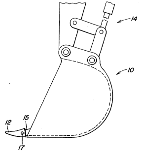
Figure 1 is a side view of a digging bucket provided with -~
the digging teeth of the present invention.
Figure 2 i8 a top view of the digging tooth.
Figure 3 is a front view of the digging tooth.
Figure 4 is a side view of the digging tooth.
Figure 5 is a bottom view of the digging tooth.
DETAILED DESCRIPTION ~ ~ ~
Excavator or backhoe bucket 10, illustrated in Figure 1, ~ ~-
i8 provided with a plurality of cutting teeth 12. Bucket 10
i5 operatively secured to an excavator by linkage 14, only a
portion of which is shown. Cutting teeth 12 are secured to
the bucket in a conventional manner. A mounting shank 15 is ~;
secured to the forward edge of the bucket and is provided with
mounting apertures. The cutting tooth i6 provided with
aligned mounting apertures 16 located in both sidewalls of the
tooth. The tooth i8 also provided with a shank receiving
cavity 18 located at the rear of the tooth. In mounting the
tooth to the bucket, the tooth i8 mounted over the mounting
shank pro~ecting from the bucket and flex pin 17 i6 inserted
through apertures 16 and the aligned apertures in the 6hank,
thereby securing the tooth to the bucket.
The bucket tooth is best illustrated in Figures 2-5. The ~-~
tooth is provided with a concave top surface 20, a convex
bottom surface 22 and two concave sidewalls 24 and 26. The~ /
top and bottom surface intersect to form forward cutting edge
28. Rear portion 28 of the tooth is provided with mounting~ ;~
means for mounting the tooth to the bucket. The mounting
means comprises mounting aperture 16 and shank receiving'." ~ ,'`'J'~
cavity 18. .~. .` ,-~
The convex bottom surface of the digging tooth -
approximately conforms to the digging arc of the bucket. As
illustrated in Figure 1, the convex bottom surface is
: , .,:
2 ~


. . :. .
. ~' .:

2~2~
substantially tangential to the bottom surface of the bucket.
sy having this convex surface, the digging tooth is not
fighting itself during a digging operation. sottom surface 22
is also hourglass shaped as defined by bottom-side edges 30
and 32 formed by bottom surface 22 with sidewalls 24 and 26,
respectively. Proceeding from the forward cutting edge to the -~
rear portion of the digging tooth, the top surface first
converges then diverges creating the hourglass shape.
The concave top surface provides digging relief as it
allows material to roll into the hollow formed by the concave
surface rather than be compressed by a flat surface. The top ~ -~
surface is also wedge shaped as defined by top-side edges 34
and 36 formed by top surface 20 with sidewalls 24 and 26, `!~'
respectively. The top surface continuously expands from the
forward cutting edge to the rear portion of the tooth. The
top portion is also provided with flat surface 38 which forms
a wear area for cutting edge 28.
I Sidewalls 24 and 26 are moldboard shaped defining concave
¦ surfaces. The sidewalls are flattened surrounding aperture 16
to facilitate mounting the tooth to the bucket.
The above described digging tooth should not be limited
by the above described embodiment but should be limited solely
by the claims that follow.


i


: . .~ . .
Representative Drawing
A single figure which represents the drawing illustrating the invention.
Administrative Status

For a clearer understanding of the status of the application/patent presented on this page, the site Disclaimer , as well as the definitions for Patent , Administrative Status , Maintenance Fee  and Payment History  should be consulted.

Administrative Status

Title Date
Forecasted Issue Date 1994-07-26
(22) Filed 1990-07-10
Examination Requested 1990-07-10
(41) Open to Public Inspection 1991-02-05
(45) Issued 1994-07-26
Deemed Expired 2010-07-10
Correction of Expired 2012-12-02

Abandonment History

There is no abandonment history.

Payment History

Fee Type Anniversary Year Due Date Amount Paid Paid Date
Application Fee $0.00 1990-07-10
Registration of a document - section 124 $0.00 1990-11-28
Maintenance Fee - Application - New Act 2 1992-07-10 $100.00 1992-07-09
Maintenance Fee - Application - New Act 3 1993-07-12 $100.00 1993-07-09
Maintenance Fee - Application - New Act 4 1994-07-11 $100.00 1994-07-08
Maintenance Fee - Patent - New Act 5 1995-07-10 $150.00 1995-07-07
Maintenance Fee - Patent - New Act 6 1996-07-10 $150.00 1996-07-09
Maintenance Fee - Patent - New Act 7 1997-07-10 $150.00 1997-07-09
Maintenance Fee - Patent - New Act 8 1998-07-10 $150.00 1998-07-09
Maintenance Fee - Patent - New Act 9 1999-07-12 $150.00 1999-07-09
Maintenance Fee - Patent - New Act 10 2000-07-10 $200.00 2000-07-07
Maintenance Fee - Patent - New Act 11 2001-07-10 $200.00 2001-07-09
Maintenance Fee - Patent - New Act 12 2002-07-10 $200.00 2002-07-09
Maintenance Fee - Patent - New Act 13 2003-07-10 $200.00 2003-07-08
Maintenance Fee - Patent - New Act 14 2004-07-12 $250.00 2004-06-21
Maintenance Fee - Patent - New Act 15 2005-07-11 $450.00 2005-06-22
Maintenance Fee - Patent - New Act 16 2006-07-10 $450.00 2006-06-19
Maintenance Fee - Patent - New Act 17 2007-07-10 $450.00 2007-06-18
Maintenance Fee - Patent - New Act 18 2008-07-10 $450.00 2008-06-18
Owners on Record

Note: Records showing the ownership history in alphabetical order.

Current Owners on Record
DEERE & COMPANY
Past Owners on Record
FELLNER, RONALD W.
Past Owners that do not appear in the "Owners on Record" listing will appear in other documentation within the application.
Documents

To view selected files, please enter reCAPTCHA code :


To view images, click a link in the Document Description column. To download the documents, select one or more checkboxes in the first column and then click the "Download Selected in PDF format (Zip Archive)" or the "Download Selected as Single PDF" button.

List of published and non-published patent-specific documents on the CPD .

If you have any difficulty accessing content, you can call the Client Service Centre at 1-866-997-1936 or send them an e-mail at CIPO Client Service Centre.


Document
Description 
Date
(yyyy-mm-dd) 
Number of pages   Size of Image (KB) 
Cover Page 1997-10-08 1 65
Abstract 1997-10-08 1 27
Claims 1997-10-08 1 46
Drawings 1997-10-08 2 146
Representative Drawing 1998-07-22 1 5
Description 1997-10-08 3 171
Office Letter 1990-11-28 1 24
PCT Correspondence 1994-04-21 1 30
Prosecution Correspondence 1993-09-21 1 47
Examiner Requisition 1993-07-05 1 61
Fees 1996-07-09 1 61
Fees 1995-07-07 1 57
Fees 1994-07-08 1 55
Fees 1993-07-09 1 34
Fees 1992-07-09 1 25