Sélection de la langue

Search

Sommaire du brevet 2020822 

Énoncé de désistement de responsabilité concernant l'information provenant de tiers

Une partie des informations de ce site Web a été fournie par des sources externes. Le gouvernement du Canada n'assume aucune responsabilité concernant la précision, l'actualité ou la fiabilité des informations fournies par les sources externes. Les utilisateurs qui désirent employer cette information devraient consulter directement la source des informations. Le contenu fourni par les sources externes n'est pas assujetti aux exigences sur les langues officielles, la protection des renseignements personnels et l'accessibilité.

Disponibilité de l'Abrégé et des Revendications

L'apparition de différences dans le texte et l'image des Revendications et de l'Abrégé dépend du moment auquel le document est publié. Les textes des Revendications et de l'Abrégé sont affichés :

  • lorsque la demande peut être examinée par le public;
  • lorsque le brevet est émis (délivrance).
(12) Brevet: (11) CA 2020822
(54) Titre français: DENT POUR MACHINE A CREUSER
(54) Titre anglais: DIGGING TOOTH ASSEMBLY
Statut: Réputé périmé
Données bibliographiques
(52) Classification canadienne des brevets (CCB):
  • 294/36
(51) Classification internationale des brevets (CIB):
  • E02F 3/36 (2006.01)
  • E02F 9/28 (2006.01)
(72) Inventeurs :
  • FELLNER, RONALD W. (Etats-Unis d'Amérique)
(73) Titulaires :
  • DEERE & COMPANY (Etats-Unis d'Amérique)
(71) Demandeurs :
(74) Agent: BORDEN LADNER GERVAIS LLP
(74) Co-agent:
(45) Délivré: 1994-07-26
(22) Date de dépôt: 1990-07-10
(41) Mise à la disponibilité du public: 1991-02-05
Requête d'examen: 1990-07-10
Licence disponible: S.O.
(25) Langue des documents déposés: Anglais

Traité de coopération en matière de brevets (PCT): Non

(30) Données de priorité de la demande:
Numéro de la demande Pays / territoire Date
07/389,655 Etats-Unis d'Amérique 1989-08-04

Abrégés

Abrégé anglais


ABSTRACT OF THE DISCLOSURE
A digging tooth for a bucket having a concave top surface
and a convex bottom surface which intersect forming a forward
cutting edge. Sidewalls connect the two surfaces and are
concave having a moldboard shape. The rear portion of the
tooth is provided with a mounting assembly for mounting it to
a bucket. The top surface continuously diverges from the
forward cutting edge to the rear portion; whereas the bottom
surface first converges than diverges from the forward cutting
edge to the rear portion.

Revendications

Note : Les revendications sont présentées dans la langue officielle dans laquelle elles ont été soumises.


The embodiments of the invention in which the exclusive
property or privilege is claimed are defined as follows:
1. A digging tooth for a digging bucket, comprising
a top concave surface;
a bottom convex surface intersecting the top surface to
form a forward cutting edge;
two moldboard sidewalls extending between the concave top
surface and the convex bottom surface, the top surface and the
two sidewalls defining two concave top-side edges, the bottom
surface and the two sidewalls defining two concave bottom-side
edges; and
a rear portion extending between the concave top surface,
the convex bottom surface and the two sidewalls, the rear
portion being provided with mounting means for mounting said
digging tooth on a digging bucket, wherein the bottom surface
proceeding from the forward cutting edge to the rear portion
first converges than diverges, and the top surface proceeding
from the forward cutting edge to the rear portion continuously

diverges.

Description

Note : Les descriptions sont présentées dans la langue officielle dans laquelle elles ont été soumises.

A DIGGING TOOTH ASSEMBLY :;
BACKGROUND OF THE INVENTION
1. Field of the Invention:
The invention is directed to improved digging teeth which
may be mounted on backhoe, excavator and/or loader buckets.
2. Description of the Prior Art:
Modern backhoes and excavators are designed to move a
bucket through an arcuate path when digging. In addition the
cutting angle of the bucket can be adjusted by manipulating
the bucket hydraulic cylinder during a digging operation.
Bucket teeth maybe added to the bucket to aid in the digging
operation.
Traditionally digging teeth have a wedge shaped
configuration. However over the years many different
configurations of digging teeth have been proposed. U.S.
Patent ~642,920 diæcloses digging teeth having a wedge-shaped
configuration and concave sides sidewalls. U.S. Patent
~'~S~7G2 discloses digging teeth having sloped sidewalls.
U.S. Patents 4,123,861, 4251,933 and 4,470,210, and U.S.
Design patent 284,010 disclose other digging teeth - -
configurations.
SU~ARY ' "
It is an object of the present invention to provide a
digging tooth configuration that more easily moves through
material thereby increasing the efficiency of the digging
bucket to which it is attached.
The digging tooth of the present invention comprises
concave top surface and a convex bottom surface that intersect
forming a forward cutting edge. The concave top surface
gros61y approximates the digging arc of the bucket. The
concave bottom surface provides material relief. Both
sidewalls of the cutting tooth have a concave or moldboard
6hape. The top surface a~ defined by the top-side edges
iormed by the sidewall6 with the top surface is hourglass
shaped. More specifically, proceeding from the forward
cutting edge to the rear portion of the digging tooth, the
top-side edges initially converge and then diverge.


. ~ : . . .

~ ~3 ~ 2 h~
..
The b~ttom surface as defined by the bottom-side edges
formed by the sidewalls with the bottom surface continuously
diverge as they proceed from the forward cutting edge to the
rear portion of the digging tooth.
BRIEF DESCRIPTION OF THE DRAWINGS
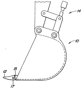
Figure 1 is a side view of a digging bucket provided with -~
the digging teeth of the present invention.
Figure 2 i8 a top view of the digging tooth.
Figure 3 is a front view of the digging tooth.
Figure 4 is a side view of the digging tooth.
Figure 5 is a bottom view of the digging tooth.
DETAILED DESCRIPTION ~ ~ ~
Excavator or backhoe bucket 10, illustrated in Figure 1, ~ ~-
i8 provided with a plurality of cutting teeth 12. Bucket 10
i5 operatively secured to an excavator by linkage 14, only a
portion of which is shown. Cutting teeth 12 are secured to
the bucket in a conventional manner. A mounting shank 15 is ~;
secured to the forward edge of the bucket and is provided with
mounting apertures. The cutting tooth i6 provided with
aligned mounting apertures 16 located in both sidewalls of the
tooth. The tooth i8 also provided with a shank receiving
cavity 18 located at the rear of the tooth. In mounting the
tooth to the bucket, the tooth i8 mounted over the mounting
shank pro~ecting from the bucket and flex pin 17 i6 inserted
through apertures 16 and the aligned apertures in the 6hank,
thereby securing the tooth to the bucket.
The bucket tooth is best illustrated in Figures 2-5. The ~-~
tooth is provided with a concave top surface 20, a convex
bottom surface 22 and two concave sidewalls 24 and 26. The~ /
top and bottom surface intersect to form forward cutting edge
28. Rear portion 28 of the tooth is provided with mounting~ ;~
means for mounting the tooth to the bucket. The mounting
means comprises mounting aperture 16 and shank receiving'." ~ ,'`'J'~
cavity 18. .~. .` ,-~
The convex bottom surface of the digging tooth -
approximately conforms to the digging arc of the bucket. As
illustrated in Figure 1, the convex bottom surface is
: , .,:
2 ~


. . :. .
. ~' .:

2~2~
substantially tangential to the bottom surface of the bucket.
sy having this convex surface, the digging tooth is not
fighting itself during a digging operation. sottom surface 22
is also hourglass shaped as defined by bottom-side edges 30
and 32 formed by bottom surface 22 with sidewalls 24 and 26,
respectively. Proceeding from the forward cutting edge to the -~
rear portion of the digging tooth, the top surface first
converges then diverges creating the hourglass shape.
The concave top surface provides digging relief as it
allows material to roll into the hollow formed by the concave
surface rather than be compressed by a flat surface. The top ~ -~
surface is also wedge shaped as defined by top-side edges 34
and 36 formed by top surface 20 with sidewalls 24 and 26, `!~'
respectively. The top surface continuously expands from the
forward cutting edge to the rear portion of the tooth. The
top portion is also provided with flat surface 38 which forms
a wear area for cutting edge 28.
I Sidewalls 24 and 26 are moldboard shaped defining concave
¦ surfaces. The sidewalls are flattened surrounding aperture 16
to facilitate mounting the tooth to the bucket.
The above described digging tooth should not be limited
by the above described embodiment but should be limited solely
by the claims that follow.


i


: . .~ . .

Dessin représentatif
Une figure unique qui représente un dessin illustrant l'invention.
États administratifs

Pour une meilleure compréhension de l'état de la demande ou brevet qui figure sur cette page, la rubrique Mise en garde , et les descriptions de Brevet , États administratifs , Taxes périodiques et Historique des paiements devraient être consultées.

États administratifs

Titre Date
Date de délivrance prévu 1994-07-26
(22) Dépôt 1990-07-10
Requête d'examen 1990-07-10
(41) Mise à la disponibilité du public 1991-02-05
(45) Délivré 1994-07-26
Réputé périmé 2010-07-10
Correction de l'état expiré 2012-12-02

Historique d'abandonnement

Il n'y a pas d'historique d'abandonnement

Historique des paiements

Type de taxes Anniversaire Échéance Montant payé Date payée
Le dépôt d'une demande de brevet 0,00 $ 1990-07-10
Enregistrement de documents 0,00 $ 1990-11-28
Taxe de maintien en état - Demande - nouvelle loi 2 1992-07-10 100,00 $ 1992-07-09
Taxe de maintien en état - Demande - nouvelle loi 3 1993-07-12 100,00 $ 1993-07-09
Taxe de maintien en état - Demande - nouvelle loi 4 1994-07-11 100,00 $ 1994-07-08
Taxe de maintien en état - brevet - nouvelle loi 5 1995-07-10 150,00 $ 1995-07-07
Taxe de maintien en état - brevet - nouvelle loi 6 1996-07-10 150,00 $ 1996-07-09
Taxe de maintien en état - brevet - nouvelle loi 7 1997-07-10 150,00 $ 1997-07-09
Taxe de maintien en état - brevet - nouvelle loi 8 1998-07-10 150,00 $ 1998-07-09
Taxe de maintien en état - brevet - nouvelle loi 9 1999-07-12 150,00 $ 1999-07-09
Taxe de maintien en état - brevet - nouvelle loi 10 2000-07-10 200,00 $ 2000-07-07
Taxe de maintien en état - brevet - nouvelle loi 11 2001-07-10 200,00 $ 2001-07-09
Taxe de maintien en état - brevet - nouvelle loi 12 2002-07-10 200,00 $ 2002-07-09
Taxe de maintien en état - brevet - nouvelle loi 13 2003-07-10 200,00 $ 2003-07-08
Taxe de maintien en état - brevet - nouvelle loi 14 2004-07-12 250,00 $ 2004-06-21
Taxe de maintien en état - brevet - nouvelle loi 15 2005-07-11 450,00 $ 2005-06-22
Taxe de maintien en état - brevet - nouvelle loi 16 2006-07-10 450,00 $ 2006-06-19
Taxe de maintien en état - brevet - nouvelle loi 17 2007-07-10 450,00 $ 2007-06-18
Taxe de maintien en état - brevet - nouvelle loi 18 2008-07-10 450,00 $ 2008-06-18
Titulaires au dossier

Les titulaires actuels et antérieures au dossier sont affichés en ordre alphabétique.

Titulaires actuels au dossier
DEERE & COMPANY
Titulaires antérieures au dossier
FELLNER, RONALD W.
Les propriétaires antérieurs qui ne figurent pas dans la liste des « Propriétaires au dossier » apparaîtront dans d'autres documents au dossier.
Documents

Pour visionner les fichiers sélectionnés, entrer le code reCAPTCHA :


Pour visualiser une image, cliquer sur un lien dans la colonne description du document. Pour télécharger l'image (les images), cliquer l'une ou plusieurs cases à cocher dans la première colonne et ensuite cliquer sur le bouton "Télécharger sélection en format PDF (archive Zip)" ou le bouton "Télécharger sélection (en un fichier PDF fusionné)".

Liste des documents de brevet publiés et non publiés sur la BDBC .

Si vous avez des difficultés à accéder au contenu, veuillez communiquer avec le Centre de services à la clientèle au 1-866-997-1936, ou envoyer un courriel au Centre de service à la clientèle de l'OPIC.


Description du
Document 
Date
(yyyy-mm-dd) 
Nombre de pages   Taille de l'image (Ko) 
Page couverture 1997-10-08 1 65
Abrégé 1997-10-08 1 27
Revendications 1997-10-08 1 46
Dessins 1997-10-08 2 146
Dessins représentatifs 1998-07-22 1 5
Description 1997-10-08 3 171
Lettre du bureau 1990-11-28 1 24
Correspondance reliée au PCT 1994-04-21 1 30
Correspondance de la poursuite 1993-09-21 1 47
Demande d'examen 1993-07-05 1 61
Taxes 1996-07-09 1 61
Taxes 1995-07-07 1 57
Taxes 1994-07-08 1 55
Taxes 1993-07-09 1 34
Taxes 1992-07-09 1 25