Language selection

Search

Patent 2021852 Summary

Third-party information liability

Some of the information on this Web page has been provided by external sources. The Government of Canada is not responsible for the accuracy, reliability or currency of the information supplied by external sources. Users wishing to rely upon this information should consult directly with the source of the information. Content provided by external sources is not subject to official languages, privacy and accessibility requirements.

Claims and Abstract availability

Any discrepancies in the text and image of the Claims and Abstract are due to differing posting times. Text of the Claims and Abstract are posted:

  • At the time the application is open to public inspection;
  • At the time of issue of the patent (grant).
(12) Patent: (11) CA 2021852
(54) English Title: FLEXIBLE DUCTING
(54) French Title: CONDUIT SOUPLE
Status: Deemed expired
Bibliographic Data
(52) Canadian Patent Classification (CPC):
  • 189/29
(51) International Patent Classification (IPC):
  • F16L 11/22 (2006.01)
  • E21F 1/04 (2006.01)
  • F16L 3/14 (2006.01)
  • F16L 9/18 (2006.01)
  • F16L 25/14 (2006.01)
  • F24F 13/02 (2006.01)
(72) Inventors :
  • EAGLETON, ANTHONY CECIL (Australia)
(73) Owners :
  • ACME GROUP PTY LTD. (Australia)
(71) Applicants :
(74) Agent:
(74) Associate agent:
(45) Issued: 1997-02-25
(22) Filed Date: 1990-07-24
(41) Open to Public Inspection: 1991-01-25
Examination requested: 1992-05-22
Availability of licence: N/A
(25) Language of filing: English

Patent Cooperation Treaty (PCT): No

(30) Application Priority Data:
Application No. Country/Territory Date
PJ5408 Australia 1989-07-24
PKO630 Australia 1990-06-14

Abstracts

English Abstract


Flexible ducting having a substantially oval and/or
elliptical cross-section comprising an intermediate
section and an end section to each end of the intermediate
section. The intermediate and end section defining two
ducts where the ducts in the intermediate section are
separated along their length by a web extending between
opposed sides of the intermediate section and the ducts at
each end section being formed as separate tubular members.
An engaging means is provided along the intermediate
section for engagement with a suspension means, and
coupling means is provided around the ducting at the ends
of the intermediate section. The tubular members are
capable of being retracted into the intermediate section
to form a female end or extending beyond the end of the
intermediate section to form a male end of the ducting.


Claims

Note: Claims are shown in the official language in which they were submitted.


The embodiments of the invention for which an
exclusive property or privilege is claimed are defined
as follows:

1. Flexible ducting having a substantially oval
and/or elliptical cross-section comprising an
intermediate section and an end section to each end of
the intermediate section, said intermediate and end
section defining two ducts where the ducts in the
intermediate section are separated along their length
by a web extending between opposed sides of the
intermediate section, the ducts at each end section
being formed as separate tubular members, an engaging
means provided along the intermediate section for
engagement with a suspension means, a coupling means
provided around the ducting at the ends of the
intermediate section said tubular members being capable
of being retracted into the intermediate section to
form a female end or extending beyond the end of the
intermediate section to form a male end of the ducting.

2. Flexible ducting as claimed in claim 1, wherein
the coupling means comprises a set of spaced webs
having eyelets therein fixed to the end of the
intermediate section.

3. Flexible ducting as claimed in claim 1, wherein
the coupling means comprises a set of spaced webs
having eyelets therein fixed to the end of the
intermediate section.

4. Flexible ducting as claimed in claim 1, 2 or 3,
wherein said web comprises a wall separating the two
ducts.

5. Flexible ducting as claimed in claim 1, 2 or 3,
wherein said web comprises a wall separating the two


ducts and the wall permits air flow between said ducts.

6. Flexible ducting as claimed in claim 1, 2 or 3,
wherein said web is formed of a mesh or net like
material.

7. Flexible air ducting as claimed in claim 1, 2,
or 3, wherein said longitudinally spaced web comprises
a set of elements extending between said opposed sides
of said ducting.

8. Flexible air ducting as claimed in claim 1, 2
or 3, wherein the engaging means is located at a
junction between one edge of the web with one side of
the ducting.

9. Flexible air ducting as claimed in claim 8,
wherein said engaging means comprises a set of
longitudinally space tabs each having an eyelet
therein.

10. Flexible air ducting as claimed in claim 8,
wherein the engaging means comprises a strip having a
set of space eyelets therein.

11. Flexible air ducting as claimed in claim 8,
wherein the engaging means comprises a hem formed at
the junction of the web and the side of the ducting.
12. Flexible ducting as claimed in claim 1, 2 or 3,
wherein said web comprises a wall separating the two
ducts and the engaging means is located at the
junction, one edge of the web with one side of the
ducting with the web comprising a wall separating the
two ducts.

13. Flexible ducting as claimed in claim 1, 2 or 3,
wherein said web comprises a wall separating the two


ducts and the engaging means is located at the junction
one edge of the web with one side of the ducting with
the web comprising a wall separating the two ducts and
wherein said engaging means comprises a set of
longitudinally space tabs each having an eyelet
therein.

14. Flexible ducting as claimed in claim 1, 2 or 3,
wherein said web comprises a wall separating the two
ducts and the engaging means is located at the junction
one edge of the web with one side of the ducting with
the web comprising a wall separating the two ducts and
wherein the engaging means comprises a strip having a
set of space eyelets therein.

15. Flexible ducting as claimed in claim 1, 2 or 3,
wherein said web comprises a wall separating the two
ducts and the engaging means is located at the junction
one edge of the web with one side of the ducting with
the web comprising a wall separating the two ducts and
wherein the engaging means comprises a hem formed at
the junction of the web and the side of the ducting.

Description

Note: Descriptions are shown in the official language in which they were submitted.


~- 2021852

THIS INVENTION relates to a flexible ducting which can be
used in closed situations such as underground mines.

When in use ventilation ducting is suspended from an
overhead cable or other suspension means.

A disadvantage with ventilation ducting currently in use
relates to the fact that most tubing is of a substantially
circular configuration and in order to provide the desired
air flow through the -tubing, it is necessary for such
tubing to be of a large diameter. Where such tubing is
used in a confined situation, such as a mine or tunnel,
the amount of head room available is reduced considerably.

It is an object of this invention to provide a ventilating
ducting which can provide the desired air flow with a
reduced profile or width compared to comparable circular
or part circular ventilating tubes currently in use.

In one form the invention resides in flexible ducting
comprising an intermediate section having a substantially
oval and/or elliptical cross-section and an end section to
each end of the intermediate section, said intermediate
and end sections defining two ducts where the ducts in the
intermediate section are separated along their length by a
web extending between opposed sides of the intermediate
section, the ducts at each end section being formed as
separate tubular members, an engaging means provided along
the intermediate section for engagement with a suspension
means, a coupling means provided around the ducting at the
ends of the intermediate section said tubular members
being capable of being retracted into the intermediate
section to form a female end or extending beyond the end
of the intermediate section to form a male end.

- 2021~2
The invention will be more fully understood in the light
of the following description of one specific embodiment.
The description is made with reference to the accompanying
drawings of which:-

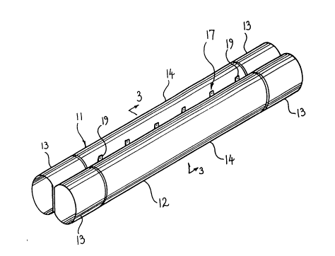
Figure 1 is a perspective view from above of aventilating tubing according to the embodiment;
Figure 2 is a perspective view from below of the
ventilating tubing;
Figure 3 is a cross-section on line 3-3 of Figure
l;
Figure 4 is a fragmentary view showing an end of
the ventilating tubing arranged as a male fitting;
Figure 5 is a fragmentary view showing an end of
the ventilating tubing arranged as a female
fitting;
Figure 6 is a perspective view of the ventilating
ducting in a collapsed condition;
Figure 7 is a schematic cross-sectional view on
line 7-7 of Figure 6;
Figure 8 is a cross-sectional view of three lengths
of flexible sheet material laid out according to
one method of forming the intermediate section;
Figure 9 is a schematic cross-sectional view of the
sheets of Figure 8 joined according to one method
of forming the intermediate section;
Figure 10 is a schematic cross-sectional view of
three sheets joined according to a second method of
forming the intermediate section; and
Figure 11 is a schematic cross-sectional view of
three sheets joined according to a third method of
forming the intermediate section.

The embodiment is directed towards ventilating ducting
which is a variation of that disclosed in Australian

2021852

Patent No. 471,926 wherein each end of the tubular member
of the tubing is formed with an extension of the hem
defining the end of the tubing which can be withdrawn from
the end of the tubing or retracted into the tubing to
define a male or female end respectively and allow for
mating interengagement of the ends of corresponding
lengths of tubing.

The embodiment is directed towards ventilation ducting
which can be used in restricted environments such as mine
shafts and tunnels whereby the depth of the space occupied
by the ventilating ducting is reduced from that of
conventional circular cross-sectioned tubing. The
embodiment comprises ducting having two ducts, 11 and 12
each being of tubular configuration and comprising an end
section 13 at each end of an intermediate section 14 which
extends for a major part of the overall length of the
tubing 14. The end sections 13 of each portion are formed
as tubular elements. The intermediate sections 14 of each
portion of the tubing share a common wall 15 throughout
their length. The common wall 15 is defined by a web of
material which extends between the upper and lower
surfaces of the tubing. If desired the common wall 15 may
be perforated to allow for a transfer of air between each
of the portions 11 and 12.

An engaging means 17 is provided along the ducting at the
upper longitudinal edge of the common wall 15 to
facilitate engaging the ventilation ducting with an
overhead suspension means such as a cable fixed to the
roof of the mine or tunnel. The engaging means 17
comprises a plurality of longitudinally spaced tabs 19
each supporting an eyelet 21. Alternatively the engaging
means may comprise a continuous strip fixed to or adjacent
the upper edge of the common wall 15 or a hem provided in

2021~52

the upper edge of the common wall, having eyelets mounted
thereto at spaced intervals.

A coupling means 23 is provided at each end of the
intermediate section 14. The coupling means 23 can
comprise a hem formed from the material of the tubing
having a series of eyelets therein, a continuous strip
having a series of eyelets therein and fixed around the
circumference of each end of the intermediate section or a
series of tabs each having an eyelet therein and fixed at
spaced intervals around the circumference of each end of
the intermediate section. To facilitate interengagement
of lengths of ducting, each tubular element extending
beyond each end of the intermediate section can be tucked
within the intermediate section of the tube as shown at
Figure 5 to define a female fitting; or the two tubular
elements 13 at one end of a length of tubing may be
withdrawn from within the tube to extend outwardly
therefrom as shown in Figure 4 to define a male fitting
for receipt within the female fitting of another length of
tubing to bring the coupling means 23 at the ends of the
intermediate sections of both lengths of ducting into
abutting relationship end of the eyelets 25 mounted in the
coupling means 23 at each abutting end of the intermediate
sections are then laced or otherwise connected together to
hold the abutting lengths of ducting in close engagement.

As a result of the embodiment, ventilating ducting is
produced which has the advantage of being flexible but
which also has the advantage of minimising the depth of
the space occupied by the ducting to increase the head
room available within the space having the ventilating
tubing in position. The ducting can be adequately
supported by the engaging means 17 disposed above the
common wall 15. Furthermore the ducting is of a unitary

i. ~
- 6 - 2021~2

configuration throughout its length since the coupling
between adjacent lengths of tubing is effected at the
abutting ends of the intermediate sections.

According to one method of forming the intermediate
section of the embodiment as shown at Figure 8, three
lengths of flexible sheet material are laid out where one
length A is to ultimately form the central wall 15 and has
a smaller width than the other common two lengths B and C
which are to define the two tubular portions 11 and 12.
The sheets are laid over each other such that one lateral
edge 30 of each sheet are aligned, and the one length A
overlies the other two lengths B and C. The lengths are
then joined together along their aligned one lateral edges
30 as shown at Figure 8. The third length C is then
relocated such that it lies to the opposite side of the
one length A from the second length B and the other
lateral edge 31 of each of the sheets are aligned and
joined to define a lip seam as shown at Figure 9 to which
the tabs 19 of the engaging means 17 are attached.

If desired any other method of assembly may be used and in
this regard Figures 10 and 11 illustrate two alternative
methods. According to the method of Figure 10 the sheets
are laid one on the other with the one length A which is
to define the central wall located between the other two
sheets and the one lateral edge 30 of each are joined.
The other lateral edges 31 are then aligned and joined.
In the case of method of Figure 11 the one sheet A and the
other two sheets B and C are laid side by side with their
lateral edges overlapping. The overlapped edges of the
other two sheets B and C are to each side of the one sheet
A. The edges 30 are then joined and then the other
lateral edges 31 are brought into alignment and joined.

_ 7 - 2021852

On completion of the intermediate section by any of the
methods designated above the tubular end section 13 are
then located inside each duct 11 and 12 at each end
thereof such that the tubular end section are each fully
received in the ducts. The coupling means 23 in the form
of a continuous strip having eyelets therein is then
applied to each end to extend around the circumference and
the coupling means 23 and end portion are then fixed to
the respective ends of the intermediate sections. To orm
a male end fitting the tubular end sections 13 are
extracted from within the intermediate section at one end
thereof.

If desired the common wall 15 may be formed of any sheet
and/or web material capable of supporting the opposed
sides of the ducting to maintain the substantially overall
cross-sectional configuration. Such web material may
comprise perforate or imperforate sheeting and mesh or net
material alternatively the common wall may comprise
longitudinally spaced elements extending between the
opposed sides. Such elements may comprise strips of any
suitable sheet and/or web material.

It should be appreciated that the scope of the present
invention need not be limited to the particular scope of
the embodiment described above.

Representative Drawing
A single figure which represents the drawing illustrating the invention.
Administrative Status

For a clearer understanding of the status of the application/patent presented on this page, the site Disclaimer , as well as the definitions for Patent , Administrative Status , Maintenance Fee  and Payment History  should be consulted.

Administrative Status

Title Date
Forecasted Issue Date 1997-02-25
(22) Filed 1990-07-24
(41) Open to Public Inspection 1991-01-25
Examination Requested 1992-05-22
(45) Issued 1997-02-25
Deemed Expired 1999-07-26

Abandonment History

There is no abandonment history.

Payment History

Fee Type Anniversary Year Due Date Amount Paid Paid Date
Application Fee $0.00 1990-07-24
Registration of a document - section 124 $0.00 1991-05-03
Maintenance Fee - Application - New Act 2 1992-07-24 $50.00 1992-05-22
Maintenance Fee - Application - New Act 3 1993-07-26 $50.00 1993-07-23
Maintenance Fee - Application - New Act 4 1994-07-25 $50.00 1994-07-20
Maintenance Fee - Application - New Act 5 1995-07-24 $75.00 1995-07-20
Maintenance Fee - Application - New Act 6 1996-07-24 $75.00 1996-07-19
Maintenance Fee - Patent - New Act 7 1997-07-24 $150.00 1997-07-24
Owners on Record

Note: Records showing the ownership history in alphabetical order.

Current Owners on Record
ACME GROUP PTY LTD.
Past Owners on Record
EAGLETON, ANTHONY CECIL
Past Owners that do not appear in the "Owners on Record" listing will appear in other documentation within the application.
Documents

To view selected files, please enter reCAPTCHA code :


To view images, click a link in the Document Description column. To download the documents, select one or more checkboxes in the first column and then click the "Download Selected in PDF format (Zip Archive)" or the "Download Selected as Single PDF" button.

List of published and non-published patent-specific documents on the CPD .

If you have any difficulty accessing content, you can call the Client Service Centre at 1-866-997-1936 or send them an e-mail at CIPO Client Service Centre.


Document
Description 
Date
(yyyy-mm-dd) 
Number of pages   Size of Image (KB) 
Abstract 1993-11-20 1 21
Cover Page 1993-11-20 1 13
Claims 1993-11-20 2 59
Drawings 1993-11-20 5 73
Description 1993-11-20 6 234
Cover Page 1997-02-20 1 14
Abstract 1997-02-20 1 23
Description 1997-02-20 6 252
Claims 1997-02-20 3 106
Drawings 1997-02-20 5 67
Representative Drawing 1999-07-15 1 15
Correspondence 1998-10-02 1 3
Fees 1997-07-24 2 59
Fees 1997-08-11 1 51
Examiner Requisition 1995-12-14 2 63
Prosecution Correspondence 1996-04-12 1 41
PCT Correspondence 1992-05-22 1 28
Office Letter 1992-06-22 1 43
PCT Correspondence 1996-12-06 1 37
Office Letter 1990-07-24 1 60
Fees 1996-07-19 1 29
Fees 1995-07-20 1 36
Fees 1994-07-20 1 33
Fees 1993-07-23 1 27
Fees 1992-05-22 1 28