Sélection de la langue

Search

Sommaire du brevet 2021852 

Énoncé de désistement de responsabilité concernant l'information provenant de tiers

Une partie des informations de ce site Web a été fournie par des sources externes. Le gouvernement du Canada n'assume aucune responsabilité concernant la précision, l'actualité ou la fiabilité des informations fournies par les sources externes. Les utilisateurs qui désirent employer cette information devraient consulter directement la source des informations. Le contenu fourni par les sources externes n'est pas assujetti aux exigences sur les langues officielles, la protection des renseignements personnels et l'accessibilité.

Disponibilité de l'Abrégé et des Revendications

L'apparition de différences dans le texte et l'image des Revendications et de l'Abrégé dépend du moment auquel le document est publié. Les textes des Revendications et de l'Abrégé sont affichés :

  • lorsque la demande peut être examinée par le public;
  • lorsque le brevet est émis (délivrance).
(12) Brevet: (11) CA 2021852
(54) Titre français: CONDUIT SOUPLE
(54) Titre anglais: FLEXIBLE DUCTING
Statut: Réputé périmé
Données bibliographiques
(52) Classification canadienne des brevets (CCB):
  • 189/29
(51) Classification internationale des brevets (CIB):
  • F16L 11/22 (2006.01)
  • E21F 1/04 (2006.01)
  • F16L 3/14 (2006.01)
  • F16L 9/18 (2006.01)
  • F16L 25/14 (2006.01)
  • F24F 13/02 (2006.01)
(72) Inventeurs :
  • EAGLETON, ANTHONY CECIL (Australie)
(73) Titulaires :
  • ACME GROUP PTY LTD. (Australie)
(71) Demandeurs :
(74) Agent:
(74) Co-agent:
(45) Délivré: 1997-02-25
(22) Date de dépôt: 1990-07-24
(41) Mise à la disponibilité du public: 1991-01-25
Requête d'examen: 1992-05-22
Licence disponible: S.O.
(25) Langue des documents déposés: Anglais

Traité de coopération en matière de brevets (PCT): Non

(30) Données de priorité de la demande:
Numéro de la demande Pays / territoire Date
PJ5408 Australie 1989-07-24
PKO630 Australie 1990-06-14

Abrégés

Abrégé anglais


Flexible ducting having a substantially oval and/or
elliptical cross-section comprising an intermediate
section and an end section to each end of the intermediate
section. The intermediate and end section defining two
ducts where the ducts in the intermediate section are
separated along their length by a web extending between
opposed sides of the intermediate section and the ducts at
each end section being formed as separate tubular members.
An engaging means is provided along the intermediate
section for engagement with a suspension means, and
coupling means is provided around the ducting at the ends
of the intermediate section. The tubular members are
capable of being retracted into the intermediate section
to form a female end or extending beyond the end of the
intermediate section to form a male end of the ducting.

Revendications

Note : Les revendications sont présentées dans la langue officielle dans laquelle elles ont été soumises.


The embodiments of the invention for which an
exclusive property or privilege is claimed are defined
as follows:

1. Flexible ducting having a substantially oval
and/or elliptical cross-section comprising an
intermediate section and an end section to each end of
the intermediate section, said intermediate and end
section defining two ducts where the ducts in the
intermediate section are separated along their length
by a web extending between opposed sides of the
intermediate section, the ducts at each end section
being formed as separate tubular members, an engaging
means provided along the intermediate section for
engagement with a suspension means, a coupling means
provided around the ducting at the ends of the
intermediate section said tubular members being capable
of being retracted into the intermediate section to
form a female end or extending beyond the end of the
intermediate section to form a male end of the ducting.

2. Flexible ducting as claimed in claim 1, wherein
the coupling means comprises a set of spaced webs
having eyelets therein fixed to the end of the
intermediate section.

3. Flexible ducting as claimed in claim 1, wherein
the coupling means comprises a set of spaced webs
having eyelets therein fixed to the end of the
intermediate section.

4. Flexible ducting as claimed in claim 1, 2 or 3,
wherein said web comprises a wall separating the two
ducts.

5. Flexible ducting as claimed in claim 1, 2 or 3,
wherein said web comprises a wall separating the two


ducts and the wall permits air flow between said ducts.

6. Flexible ducting as claimed in claim 1, 2 or 3,
wherein said web is formed of a mesh or net like
material.

7. Flexible air ducting as claimed in claim 1, 2,
or 3, wherein said longitudinally spaced web comprises
a set of elements extending between said opposed sides
of said ducting.

8. Flexible air ducting as claimed in claim 1, 2
or 3, wherein the engaging means is located at a
junction between one edge of the web with one side of
the ducting.

9. Flexible air ducting as claimed in claim 8,
wherein said engaging means comprises a set of
longitudinally space tabs each having an eyelet
therein.

10. Flexible air ducting as claimed in claim 8,
wherein the engaging means comprises a strip having a
set of space eyelets therein.

11. Flexible air ducting as claimed in claim 8,
wherein the engaging means comprises a hem formed at
the junction of the web and the side of the ducting.
12. Flexible ducting as claimed in claim 1, 2 or 3,
wherein said web comprises a wall separating the two
ducts and the engaging means is located at the
junction, one edge of the web with one side of the
ducting with the web comprising a wall separating the
two ducts.

13. Flexible ducting as claimed in claim 1, 2 or 3,
wherein said web comprises a wall separating the two


ducts and the engaging means is located at the junction
one edge of the web with one side of the ducting with
the web comprising a wall separating the two ducts and
wherein said engaging means comprises a set of
longitudinally space tabs each having an eyelet
therein.

14. Flexible ducting as claimed in claim 1, 2 or 3,
wherein said web comprises a wall separating the two
ducts and the engaging means is located at the junction
one edge of the web with one side of the ducting with
the web comprising a wall separating the two ducts and
wherein the engaging means comprises a strip having a
set of space eyelets therein.

15. Flexible ducting as claimed in claim 1, 2 or 3,
wherein said web comprises a wall separating the two
ducts and the engaging means is located at the junction
one edge of the web with one side of the ducting with
the web comprising a wall separating the two ducts and
wherein the engaging means comprises a hem formed at
the junction of the web and the side of the ducting.

Description

Note : Les descriptions sont présentées dans la langue officielle dans laquelle elles ont été soumises.


~- 2021852

THIS INVENTION relates to a flexible ducting which can be
used in closed situations such as underground mines.

When in use ventilation ducting is suspended from an
overhead cable or other suspension means.

A disadvantage with ventilation ducting currently in use
relates to the fact that most tubing is of a substantially
circular configuration and in order to provide the desired
air flow through the -tubing, it is necessary for such
tubing to be of a large diameter. Where such tubing is
used in a confined situation, such as a mine or tunnel,
the amount of head room available is reduced considerably.

It is an object of this invention to provide a ventilating
ducting which can provide the desired air flow with a
reduced profile or width compared to comparable circular
or part circular ventilating tubes currently in use.

In one form the invention resides in flexible ducting
comprising an intermediate section having a substantially
oval and/or elliptical cross-section and an end section to
each end of the intermediate section, said intermediate
and end sections defining two ducts where the ducts in the
intermediate section are separated along their length by a
web extending between opposed sides of the intermediate
section, the ducts at each end section being formed as
separate tubular members, an engaging means provided along
the intermediate section for engagement with a suspension
means, a coupling means provided around the ducting at the
ends of the intermediate section said tubular members
being capable of being retracted into the intermediate
section to form a female end or extending beyond the end
of the intermediate section to form a male end.

- 2021~2
The invention will be more fully understood in the light
of the following description of one specific embodiment.
The description is made with reference to the accompanying
drawings of which:-

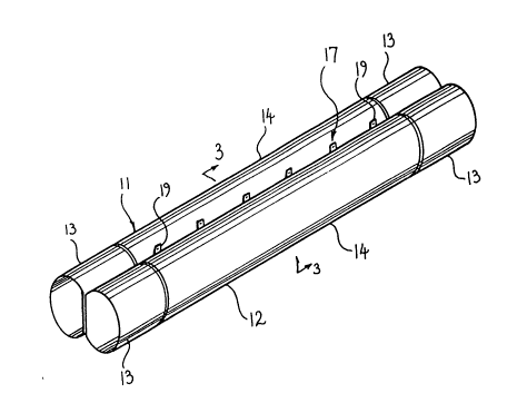
Figure 1 is a perspective view from above of aventilating tubing according to the embodiment;
Figure 2 is a perspective view from below of the
ventilating tubing;
Figure 3 is a cross-section on line 3-3 of Figure
l;
Figure 4 is a fragmentary view showing an end of
the ventilating tubing arranged as a male fitting;
Figure 5 is a fragmentary view showing an end of
the ventilating tubing arranged as a female
fitting;
Figure 6 is a perspective view of the ventilating
ducting in a collapsed condition;
Figure 7 is a schematic cross-sectional view on
line 7-7 of Figure 6;
Figure 8 is a cross-sectional view of three lengths
of flexible sheet material laid out according to
one method of forming the intermediate section;
Figure 9 is a schematic cross-sectional view of the
sheets of Figure 8 joined according to one method
of forming the intermediate section;
Figure 10 is a schematic cross-sectional view of
three sheets joined according to a second method of
forming the intermediate section; and
Figure 11 is a schematic cross-sectional view of
three sheets joined according to a third method of
forming the intermediate section.

The embodiment is directed towards ventilating ducting
which is a variation of that disclosed in Australian

2021852

Patent No. 471,926 wherein each end of the tubular member
of the tubing is formed with an extension of the hem
defining the end of the tubing which can be withdrawn from
the end of the tubing or retracted into the tubing to
define a male or female end respectively and allow for
mating interengagement of the ends of corresponding
lengths of tubing.

The embodiment is directed towards ventilation ducting
which can be used in restricted environments such as mine
shafts and tunnels whereby the depth of the space occupied
by the ventilating ducting is reduced from that of
conventional circular cross-sectioned tubing. The
embodiment comprises ducting having two ducts, 11 and 12
each being of tubular configuration and comprising an end
section 13 at each end of an intermediate section 14 which
extends for a major part of the overall length of the
tubing 14. The end sections 13 of each portion are formed
as tubular elements. The intermediate sections 14 of each
portion of the tubing share a common wall 15 throughout
their length. The common wall 15 is defined by a web of
material which extends between the upper and lower
surfaces of the tubing. If desired the common wall 15 may
be perforated to allow for a transfer of air between each
of the portions 11 and 12.

An engaging means 17 is provided along the ducting at the
upper longitudinal edge of the common wall 15 to
facilitate engaging the ventilation ducting with an
overhead suspension means such as a cable fixed to the
roof of the mine or tunnel. The engaging means 17
comprises a plurality of longitudinally spaced tabs 19
each supporting an eyelet 21. Alternatively the engaging
means may comprise a continuous strip fixed to or adjacent
the upper edge of the common wall 15 or a hem provided in

2021~52

the upper edge of the common wall, having eyelets mounted
thereto at spaced intervals.

A coupling means 23 is provided at each end of the
intermediate section 14. The coupling means 23 can
comprise a hem formed from the material of the tubing
having a series of eyelets therein, a continuous strip
having a series of eyelets therein and fixed around the
circumference of each end of the intermediate section or a
series of tabs each having an eyelet therein and fixed at
spaced intervals around the circumference of each end of
the intermediate section. To facilitate interengagement
of lengths of ducting, each tubular element extending
beyond each end of the intermediate section can be tucked
within the intermediate section of the tube as shown at
Figure 5 to define a female fitting; or the two tubular
elements 13 at one end of a length of tubing may be
withdrawn from within the tube to extend outwardly
therefrom as shown in Figure 4 to define a male fitting
for receipt within the female fitting of another length of
tubing to bring the coupling means 23 at the ends of the
intermediate sections of both lengths of ducting into
abutting relationship end of the eyelets 25 mounted in the
coupling means 23 at each abutting end of the intermediate
sections are then laced or otherwise connected together to
hold the abutting lengths of ducting in close engagement.

As a result of the embodiment, ventilating ducting is
produced which has the advantage of being flexible but
which also has the advantage of minimising the depth of
the space occupied by the ducting to increase the head
room available within the space having the ventilating
tubing in position. The ducting can be adequately
supported by the engaging means 17 disposed above the
common wall 15. Furthermore the ducting is of a unitary

i. ~
- 6 - 2021~2

configuration throughout its length since the coupling
between adjacent lengths of tubing is effected at the
abutting ends of the intermediate sections.

According to one method of forming the intermediate
section of the embodiment as shown at Figure 8, three
lengths of flexible sheet material are laid out where one
length A is to ultimately form the central wall 15 and has
a smaller width than the other common two lengths B and C
which are to define the two tubular portions 11 and 12.
The sheets are laid over each other such that one lateral
edge 30 of each sheet are aligned, and the one length A
overlies the other two lengths B and C. The lengths are
then joined together along their aligned one lateral edges
30 as shown at Figure 8. The third length C is then
relocated such that it lies to the opposite side of the
one length A from the second length B and the other
lateral edge 31 of each of the sheets are aligned and
joined to define a lip seam as shown at Figure 9 to which
the tabs 19 of the engaging means 17 are attached.

If desired any other method of assembly may be used and in
this regard Figures 10 and 11 illustrate two alternative
methods. According to the method of Figure 10 the sheets
are laid one on the other with the one length A which is
to define the central wall located between the other two
sheets and the one lateral edge 30 of each are joined.
The other lateral edges 31 are then aligned and joined.
In the case of method of Figure 11 the one sheet A and the
other two sheets B and C are laid side by side with their
lateral edges overlapping. The overlapped edges of the
other two sheets B and C are to each side of the one sheet
A. The edges 30 are then joined and then the other
lateral edges 31 are brought into alignment and joined.

_ 7 - 2021852

On completion of the intermediate section by any of the
methods designated above the tubular end section 13 are
then located inside each duct 11 and 12 at each end
thereof such that the tubular end section are each fully
received in the ducts. The coupling means 23 in the form
of a continuous strip having eyelets therein is then
applied to each end to extend around the circumference and
the coupling means 23 and end portion are then fixed to
the respective ends of the intermediate sections. To orm
a male end fitting the tubular end sections 13 are
extracted from within the intermediate section at one end
thereof.

If desired the common wall 15 may be formed of any sheet
and/or web material capable of supporting the opposed
sides of the ducting to maintain the substantially overall
cross-sectional configuration. Such web material may
comprise perforate or imperforate sheeting and mesh or net
material alternatively the common wall may comprise
longitudinally spaced elements extending between the
opposed sides. Such elements may comprise strips of any
suitable sheet and/or web material.

It should be appreciated that the scope of the present
invention need not be limited to the particular scope of
the embodiment described above.

Dessin représentatif
Une figure unique qui représente un dessin illustrant l'invention.
États administratifs

Pour une meilleure compréhension de l'état de la demande ou brevet qui figure sur cette page, la rubrique Mise en garde , et les descriptions de Brevet , États administratifs , Taxes périodiques et Historique des paiements devraient être consultées.

États administratifs

Titre Date
Date de délivrance prévu 1997-02-25
(22) Dépôt 1990-07-24
(41) Mise à la disponibilité du public 1991-01-25
Requête d'examen 1992-05-22
(45) Délivré 1997-02-25
Réputé périmé 1999-07-26

Historique d'abandonnement

Il n'y a pas d'historique d'abandonnement

Historique des paiements

Type de taxes Anniversaire Échéance Montant payé Date payée
Le dépôt d'une demande de brevet 0,00 $ 1990-07-24
Enregistrement de documents 0,00 $ 1991-05-03
Taxe de maintien en état - Demande - nouvelle loi 2 1992-07-24 50,00 $ 1992-05-22
Taxe de maintien en état - Demande - nouvelle loi 3 1993-07-26 50,00 $ 1993-07-23
Taxe de maintien en état - Demande - nouvelle loi 4 1994-07-25 50,00 $ 1994-07-20
Taxe de maintien en état - Demande - nouvelle loi 5 1995-07-24 75,00 $ 1995-07-20
Taxe de maintien en état - Demande - nouvelle loi 6 1996-07-24 75,00 $ 1996-07-19
Taxe de maintien en état - brevet - nouvelle loi 7 1997-07-24 150,00 $ 1997-07-24
Titulaires au dossier

Les titulaires actuels et antérieures au dossier sont affichés en ordre alphabétique.

Titulaires actuels au dossier
ACME GROUP PTY LTD.
Titulaires antérieures au dossier
EAGLETON, ANTHONY CECIL
Les propriétaires antérieurs qui ne figurent pas dans la liste des « Propriétaires au dossier » apparaîtront dans d'autres documents au dossier.
Documents

Pour visionner les fichiers sélectionnés, entrer le code reCAPTCHA :


Pour visualiser une image, cliquer sur un lien dans la colonne description du document. Pour télécharger l'image (les images), cliquer l'une ou plusieurs cases à cocher dans la première colonne et ensuite cliquer sur le bouton "Télécharger sélection en format PDF (archive Zip)" ou le bouton "Télécharger sélection (en un fichier PDF fusionné)".

Liste des documents de brevet publiés et non publiés sur la BDBC .

Si vous avez des difficultés à accéder au contenu, veuillez communiquer avec le Centre de services à la clientèle au 1-866-997-1936, ou envoyer un courriel au Centre de service à la clientèle de l'OPIC.


Description du
Document 
Date
(yyyy-mm-dd) 
Nombre de pages   Taille de l'image (Ko) 
Abrégé 1993-11-20 1 21
Page couverture 1993-11-20 1 13
Revendications 1993-11-20 2 59
Dessins 1993-11-20 5 73
Description 1993-11-20 6 234
Page couverture 1997-02-20 1 14
Abrégé 1997-02-20 1 23
Description 1997-02-20 6 252
Revendications 1997-02-20 3 106
Dessins 1997-02-20 5 67
Dessins représentatifs 1999-07-15 1 15
Correspondance 1998-10-02 1 3
Taxes 1997-07-24 2 59
Taxes 1997-08-11 1 51
Demande d'examen 1995-12-14 2 63
Correspondance de la poursuite 1996-04-12 1 41
Correspondance reliée au PCT 1992-05-22 1 28
Lettre du bureau 1992-06-22 1 43
Correspondance reliée au PCT 1996-12-06 1 37
Lettre du bureau 1990-07-24 1 60
Taxes 1996-07-19 1 29
Taxes 1995-07-20 1 36
Taxes 1994-07-20 1 33
Taxes 1993-07-23 1 27
Taxes 1992-05-22 1 28