Language selection

Search

Patent 2023180 Summary

Third-party information liability

Some of the information on this Web page has been provided by external sources. The Government of Canada is not responsible for the accuracy, reliability or currency of the information supplied by external sources. Users wishing to rely upon this information should consult directly with the source of the information. Content provided by external sources is not subject to official languages, privacy and accessibility requirements.

Claims and Abstract availability

Any discrepancies in the text and image of the Claims and Abstract are due to differing posting times. Text of the Claims and Abstract are posted:

  • At the time the application is open to public inspection;
  • At the time of issue of the patent (grant).
(12) Patent: (11) CA 2023180
(54) English Title: STRUCTURE OF BICYCLE CHAIN TRANSMISSION
(54) French Title: TRANSMISSION PAR CHAINE, POUR BICYCLETTE
Status: Deemed expired
Bibliographic Data
(52) Canadian Patent Classification (CPC):
  • 74/35
(51) International Patent Classification (IPC):
  • B62M 3/04 (2006.01)
  • B62M 3/06 (2006.01)
(72) Inventors :
  • WU, CHING-RONG (Taiwan, Province of China)
(73) Owners :
  • WU, CHING-RONG (Taiwan, Province of China)
(71) Applicants :
(74) Agent: KIRBY EADES GALE BAKER
(74) Associate agent:
(45) Issued: 1994-04-26
(22) Filed Date: 1990-08-13
(41) Open to Public Inspection: 1992-02-14
Examination requested: 1991-01-17
Availability of licence: N/A
(25) Language of filing: English

Patent Cooperation Treaty (PCT): No

(30) Application Priority Data: None

Abstracts

English Abstract


STRUCTURE OF BICYCLE CHAIN TRANSMISSION


ABSTRACT:
Disclosed is a bicycle chain transmission, which
comprises a crank fastened in a bearing block on the outer
side of a chain wheel and connected with a side projection of
a ball bearing which is mounted on a connector which is
eccentrically fastened in the bottom bracket axle of a
bicycle. The rotation of the connector drives the ball
bearing to rotate eccentrically and to drive the crank to
automatically change its arm of force so as to minimize
energy consumption in pedaling.


Claims

Note: Claims are shown in the official language in which they were submitted.


CLAIM:
1. A bicycle chain transmission, comprising:
a bottom bracket bearing device comprised of a
connector, a hub, a bush and a ball bearing, said connector
comprising a projection extending forward at one end for
fastening in the bottom bracket of a bicycle, an eccentric
hole piercing therethrough for the insertion therethrough of
the bottom bracket axle of a bicycle, and a circular groove
on its outer wall surface for mounting said bush and said
said ball bearing, said ball bearing comprising a side
projection, and a plurality of steel balls fastened in its
inner wall surface between said bush permitting said ball
bearing to follow said connector to rotate clockwise or to
make idle running in counter-clockwise direction;
a chain wheel mounted on said bottom bracket axle,
comprising a bearing block at an outer side, said bearing
block having a hole vertically made thereon with two bearings
fastened therein at two opposite ends; and
a crank movably fastened in the two bearings of
said bearing block of said chain wheel, having a pedal
rotatably secured thereto at one end for pedaling to drive
said crank to carry said chain wheel to rotate via said


bottom bracket bearing device, and a fastening member at an
opposite end for the connection thereto of said unitary side
projection of said ball bearing by a lock pin;
characterized in that the rotation of said
connector drives said ball bearing to rotate eccentrically
and to drive said crank to automatically change its arm of
force so as to minimize energy consumption in pedaling.

Description

Note: Descriptions are shown in the official language in which they were submitted.


STRUCTURE OF BICYCLE CHAIN TRANSMISSION
.~
BACKGROUND OF THE INYENTION
The present invention is related to bicycle chain
transmissions and more particularly to a bicycle chain
transmission the arm of force of the pedal crank of Nhich is
automatically changed so as to minimize energy consumption in
pedaling.

In a regular bicycle chain transmission, a crank
is genarally fastened in a chain wheel at the center.
During pedaling, the arm of force of a crank does not make
any change. As it is known that longer arm of force of a
crank can minimize energy consumption in forNard pedaling.
Therefore, there is a kind of chain structure designed in
oval shape 60 that tho arm of force of a crank can be
automatically changed during its rotation. This type of
design can effcctively minimize energy consumption in
pedaling. HoNever, a chain maY b~ easily disengagQd from an
oval shape of chain whQel during rotation.


~ ,.
.~ ,.,, :
~' ., .,-;. . - ;, :
: . :~'. - , . , '
. ~ -
-, .
..


~,
SU~MARY OF THE INVENTION:
The present invantion has been accomplished under
the circumstances in view. It is one obiect of the Present
invention to provide a bicycle chain transmission which can
drive a bicycle to run with less labor and without causing a
chain to disengage.

According to the present invention, a bicycle
~ chain transmission comprises a bottom bracket bearing device
3 eccentrically mounted on a bottom bracket bearing axle and
¦ coupled with a crank and a chain wheel. The chain wheel is
movably fastened in a bearin8 block at one side of the chain
wheel so that its arm of force is changed according to its
position during the eccentric rotation of the bottom bracket
bearing device to minimize energy consumption in pedaling.

~RIEF DESCRIPTION OF THE DRAWINGS:
Fig, 1 is a plan view of a bicycle chain wheel
according ta the prior art;
Fig, 2 is a perspective fragmentary view of a
bicycle chain wheel embodying the present invention;
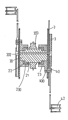
Fig. 3 is a sectional assembly view of the present


. .
,

r~


invantion;
Figs. 4-6 illustrate the operation of the present
invention.

DETAILED DESCRIPTION OF THE [REFERRED EMBODIMENT:
Referring to Figs. 2 and 3, a bicycle chain
transmission in accordance with the present invention is
generally comprised of a bottom bracket bearing device 2, a
chain wheel 3 and a crank 4. The bottom bracket bearing
device 2 is comprised of a cnnnector 20, a hub 21, a bush 22
and a ball beariDg 23. The connector 20 comprises a
projection 200 ext0nding forward at one end for fastening in
the bottom bracket 203 of a bicycle and having an eccentric
hole 201 Piercing therethrough for the insertion therethrough
of the bottom bracket axle 202 of a bicycle to secure the
bottom bracket bearing device 2 to the chain wheel 3. A
circular groove 204 is made on the connector 20 for mounting
the bush 22 so that the ball bearing 23 can be fastened
thereto. A plurality of steel balls 230 are fastened in the
inner wall surface of the ball bearing 23 and set between the
ball bearing 23 and the bush 22, such that the ball bearing
23 is permitted to follow the connector 20 to rotate


,::


....
. .. ,-~ .

~t ~ tj ~


clockwise or to make idle running in counter-clockwise
direction. The ball bearing 23 has an unitary side
projection 231 fastened in the chain Nheel 3 to connect to a
connection member 40 on the crank 4 by a lock Pin 400. The
chain wheel 3 comprises a bearing block 30 with two bearings
41 fastened therein at tNo opposite ends for movably mounting
the crank 4. The crank 4 has a pedal 42 fixedlY secured
thereto at one end through which the crank 4 is pedaled to
carry the chain wheel 3 to rotate.

The oPeration of the present invention is outlined
hereinafter with reference to Figs. 4 through 6. When the
pedal 42 is pedaled to rotate the crank 4 from its upper
vertical position to a lower vertical position, the ball
bearing 23 is carried by the connector 20 to rotate
eccentrically around a wider circle. During eccentric
rotation of the ball bearing 23 from, the side projection 231
is simultaneously pushed forward to increase the arm of force
of crank 4 so as to minimize energy consumption. As soon
as the crank is moved to a lower vertical position, the
eccentric rotation of the connector 20 relatively shortens
the arm of force of the crank 4. After the crank 4 is


~ , - .


rotated to a backward positian its arm of force is in the
shortest condition so that it can be efficiently rotated to
the uPPer vertical position for repeated rotation.

As described abave, the present invention is to
provide such a bicycle chain transmission, in which the arm
of force of the crank is automatically adiusted during its
rotation so as to minimize energy consumption in pedaling.


:
.. - ' ` ' .
,,~,.

Representative Drawing
A single figure which represents the drawing illustrating the invention.
Administrative Status

For a clearer understanding of the status of the application/patent presented on this page, the site Disclaimer , as well as the definitions for Patent , Administrative Status , Maintenance Fee  and Payment History  should be consulted.

Administrative Status

Title Date
Forecasted Issue Date 1994-04-26
(22) Filed 1990-08-13
Examination Requested 1991-01-17
(41) Open to Public Inspection 1992-02-14
(45) Issued 1994-04-26
Deemed Expired 1996-02-13

Abandonment History

There is no abandonment history.

Payment History

Fee Type Anniversary Year Due Date Amount Paid Paid Date
Application Fee $0.00 1990-08-13
Maintenance Fee - Application - New Act 2 1992-08-13 $50.00 1992-08-06
Maintenance Fee - Application - New Act 3 1993-08-13 $50.00 1993-08-13
Maintenance Fee - Patent - New Act 4 1994-08-15 $50.00 1994-08-05
Owners on Record

Note: Records showing the ownership history in alphabetical order.

Current Owners on Record
WU, CHING-RONG
Past Owners on Record
None
Past Owners that do not appear in the "Owners on Record" listing will appear in other documentation within the application.
Documents

To view selected files, please enter reCAPTCHA code :


To view images, click a link in the Document Description column. To download the documents, select one or more checkboxes in the first column and then click the "Download Selected in PDF format (Zip Archive)" or the "Download Selected as Single PDF" button.

List of published and non-published patent-specific documents on the CPD .

If you have any difficulty accessing content, you can call the Client Service Centre at 1-866-997-1936 or send them an e-mail at CIPO Client Service Centre.


Document
Description 
Date
(yyyy-mm-dd) 
Number of pages   Size of Image (KB) 
Description 1994-07-09 5 115
Cover Page 1994-07-09 1 18
Representative Drawing 1999-06-30 1 10
Abstract 1994-07-09 1 13
Claims 1994-07-09 2 40
Drawings 1994-07-09 2 53
Office Letter 1991-04-10 1 22
PCT Correspondence 1994-01-31 1 37
Examiner Requisition 1993-01-25 1 57
Prosecution Correspondence 1991-01-17 1 45
Prosecution Correspondence 1993-06-25 2 64
Fees 1994-08-05 1 72
Fees 1993-08-13 1 45
Fees 1992-08-06 1 41