Sélection de la langue

Search

Sommaire du brevet 2023180 

Énoncé de désistement de responsabilité concernant l'information provenant de tiers

Une partie des informations de ce site Web a été fournie par des sources externes. Le gouvernement du Canada n'assume aucune responsabilité concernant la précision, l'actualité ou la fiabilité des informations fournies par les sources externes. Les utilisateurs qui désirent employer cette information devraient consulter directement la source des informations. Le contenu fourni par les sources externes n'est pas assujetti aux exigences sur les langues officielles, la protection des renseignements personnels et l'accessibilité.

Disponibilité de l'Abrégé et des Revendications

L'apparition de différences dans le texte et l'image des Revendications et de l'Abrégé dépend du moment auquel le document est publié. Les textes des Revendications et de l'Abrégé sont affichés :

  • lorsque la demande peut être examinée par le public;
  • lorsque le brevet est émis (délivrance).
(12) Brevet: (11) CA 2023180
(54) Titre français: TRANSMISSION PAR CHAINE, POUR BICYCLETTE
(54) Titre anglais: STRUCTURE OF BICYCLE CHAIN TRANSMISSION
Statut: Réputé périmé
Données bibliographiques
Abrégés

Abrégé anglais


STRUCTURE OF BICYCLE CHAIN TRANSMISSION


ABSTRACT:
Disclosed is a bicycle chain transmission, which
comprises a crank fastened in a bearing block on the outer
side of a chain wheel and connected with a side projection of
a ball bearing which is mounted on a connector which is
eccentrically fastened in the bottom bracket axle of a
bicycle. The rotation of the connector drives the ball
bearing to rotate eccentrically and to drive the crank to
automatically change its arm of force so as to minimize
energy consumption in pedaling.

Revendications

Note : Les revendications sont présentées dans la langue officielle dans laquelle elles ont été soumises.


CLAIM:
1. A bicycle chain transmission, comprising:
a bottom bracket bearing device comprised of a
connector, a hub, a bush and a ball bearing, said connector
comprising a projection extending forward at one end for
fastening in the bottom bracket of a bicycle, an eccentric
hole piercing therethrough for the insertion therethrough of
the bottom bracket axle of a bicycle, and a circular groove
on its outer wall surface for mounting said bush and said
said ball bearing, said ball bearing comprising a side
projection, and a plurality of steel balls fastened in its
inner wall surface between said bush permitting said ball
bearing to follow said connector to rotate clockwise or to
make idle running in counter-clockwise direction;
a chain wheel mounted on said bottom bracket axle,
comprising a bearing block at an outer side, said bearing
block having a hole vertically made thereon with two bearings
fastened therein at two opposite ends; and
a crank movably fastened in the two bearings of
said bearing block of said chain wheel, having a pedal
rotatably secured thereto at one end for pedaling to drive
said crank to carry said chain wheel to rotate via said


bottom bracket bearing device, and a fastening member at an
opposite end for the connection thereto of said unitary side
projection of said ball bearing by a lock pin;
characterized in that the rotation of said
connector drives said ball bearing to rotate eccentrically
and to drive said crank to automatically change its arm of
force so as to minimize energy consumption in pedaling.

Description

Note : Les descriptions sont présentées dans la langue officielle dans laquelle elles ont été soumises.


STRUCTURE OF BICYCLE CHAIN TRANSMISSION
.~
BACKGROUND OF THE INYENTION
The present invention is related to bicycle chain
transmissions and more particularly to a bicycle chain
transmission the arm of force of the pedal crank of Nhich is
automatically changed so as to minimize energy consumption in
pedaling.

In a regular bicycle chain transmission, a crank
is genarally fastened in a chain wheel at the center.
During pedaling, the arm of force of a crank does not make
any change. As it is known that longer arm of force of a
crank can minimize energy consumption in forNard pedaling.
Therefore, there is a kind of chain structure designed in
oval shape 60 that tho arm of force of a crank can be
automatically changed during its rotation. This type of
design can effcctively minimize energy consumption in
pedaling. HoNever, a chain maY b~ easily disengagQd from an
oval shape of chain whQel during rotation.


~ ,.
.~ ,.,, :
~' ., .,-;. . - ;, :
: . :~'. - , . , '
. ~ -
-, .
..


~,
SU~MARY OF THE INVENTION:
The present invantion has been accomplished under
the circumstances in view. It is one obiect of the Present
invention to provide a bicycle chain transmission which can
drive a bicycle to run with less labor and without causing a
chain to disengage.

According to the present invention, a bicycle
~ chain transmission comprises a bottom bracket bearing device
3 eccentrically mounted on a bottom bracket bearing axle and
¦ coupled with a crank and a chain wheel. The chain wheel is
movably fastened in a bearin8 block at one side of the chain
wheel so that its arm of force is changed according to its
position during the eccentric rotation of the bottom bracket
bearing device to minimize energy consumption in pedaling.

~RIEF DESCRIPTION OF THE DRAWINGS:
Fig, 1 is a plan view of a bicycle chain wheel
according ta the prior art;
Fig, 2 is a perspective fragmentary view of a
bicycle chain wheel embodying the present invention;
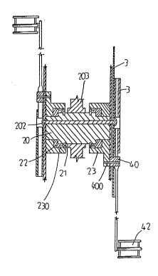
Fig. 3 is a sectional assembly view of the present


. .
,

r~


invantion;
Figs. 4-6 illustrate the operation of the present
invention.

DETAILED DESCRIPTION OF THE [REFERRED EMBODIMENT:
Referring to Figs. 2 and 3, a bicycle chain
transmission in accordance with the present invention is
generally comprised of a bottom bracket bearing device 2, a
chain wheel 3 and a crank 4. The bottom bracket bearing
device 2 is comprised of a cnnnector 20, a hub 21, a bush 22
and a ball beariDg 23. The connector 20 comprises a
projection 200 ext0nding forward at one end for fastening in
the bottom bracket 203 of a bicycle and having an eccentric
hole 201 Piercing therethrough for the insertion therethrough
of the bottom bracket axle 202 of a bicycle to secure the
bottom bracket bearing device 2 to the chain wheel 3. A
circular groove 204 is made on the connector 20 for mounting
the bush 22 so that the ball bearing 23 can be fastened
thereto. A plurality of steel balls 230 are fastened in the
inner wall surface of the ball bearing 23 and set between the
ball bearing 23 and the bush 22, such that the ball bearing
23 is permitted to follow the connector 20 to rotate


,::


....
. .. ,-~ .

~t ~ tj ~


clockwise or to make idle running in counter-clockwise
direction. The ball bearing 23 has an unitary side
projection 231 fastened in the chain Nheel 3 to connect to a
connection member 40 on the crank 4 by a lock Pin 400. The
chain wheel 3 comprises a bearing block 30 with two bearings
41 fastened therein at tNo opposite ends for movably mounting
the crank 4. The crank 4 has a pedal 42 fixedlY secured
thereto at one end through which the crank 4 is pedaled to
carry the chain wheel 3 to rotate.

The oPeration of the present invention is outlined
hereinafter with reference to Figs. 4 through 6. When the
pedal 42 is pedaled to rotate the crank 4 from its upper
vertical position to a lower vertical position, the ball
bearing 23 is carried by the connector 20 to rotate
eccentrically around a wider circle. During eccentric
rotation of the ball bearing 23 from, the side projection 231
is simultaneously pushed forward to increase the arm of force
of crank 4 so as to minimize energy consumption. As soon
as the crank is moved to a lower vertical position, the
eccentric rotation of the connector 20 relatively shortens
the arm of force of the crank 4. After the crank 4 is


~ , - .


rotated to a backward positian its arm of force is in the
shortest condition so that it can be efficiently rotated to
the uPPer vertical position for repeated rotation.

As described abave, the present invention is to
provide such a bicycle chain transmission, in which the arm
of force of the crank is automatically adiusted during its
rotation so as to minimize energy consumption in pedaling.


:
.. - ' ` ' .
,,~,.

Dessin représentatif
Une figure unique qui représente un dessin illustrant l'invention.
États administratifs

Pour une meilleure compréhension de l'état de la demande ou brevet qui figure sur cette page, la rubrique Mise en garde , et les descriptions de Brevet , États administratifs , Taxes périodiques et Historique des paiements devraient être consultées.

États administratifs

Titre Date
Date de délivrance prévu 1994-04-26
(22) Dépôt 1990-08-13
Requête d'examen 1991-01-17
(41) Mise à la disponibilité du public 1992-02-14
(45) Délivré 1994-04-26
Réputé périmé 1996-02-13

Historique d'abandonnement

Il n'y a pas d'historique d'abandonnement

Historique des paiements

Type de taxes Anniversaire Échéance Montant payé Date payée
Le dépôt d'une demande de brevet 0,00 $ 1990-08-13
Taxe de maintien en état - Demande - nouvelle loi 2 1992-08-13 50,00 $ 1992-08-06
Taxe de maintien en état - Demande - nouvelle loi 3 1993-08-13 50,00 $ 1993-08-13
Taxe de maintien en état - brevet - nouvelle loi 4 1994-08-15 50,00 $ 1994-08-05
Titulaires au dossier

Les titulaires actuels et antérieures au dossier sont affichés en ordre alphabétique.

Titulaires actuels au dossier
WU, CHING-RONG
Titulaires antérieures au dossier
S.O.
Les propriétaires antérieurs qui ne figurent pas dans la liste des « Propriétaires au dossier » apparaîtront dans d'autres documents au dossier.
Documents

Pour visionner les fichiers sélectionnés, entrer le code reCAPTCHA :


Pour visualiser une image, cliquer sur un lien dans la colonne description du document. Pour télécharger l'image (les images), cliquer l'une ou plusieurs cases à cocher dans la première colonne et ensuite cliquer sur le bouton "Télécharger sélection en format PDF (archive Zip)" ou le bouton "Télécharger sélection (en un fichier PDF fusionné)".

Liste des documents de brevet publiés et non publiés sur la BDBC .

Si vous avez des difficultés à accéder au contenu, veuillez communiquer avec le Centre de services à la clientèle au 1-866-997-1936, ou envoyer un courriel au Centre de service à la clientèle de l'OPIC.


Description du
Document 
Date
(yyyy-mm-dd) 
Nombre de pages   Taille de l'image (Ko) 
Description 1994-07-09 5 115
Page couverture 1994-07-09 1 18
Dessins représentatifs 1999-06-30 1 10
Abrégé 1994-07-09 1 13
Revendications 1994-07-09 2 40
Dessins 1994-07-09 2 53
Lettre du bureau 1991-04-10 1 22
Correspondance reliée au PCT 1994-01-31 1 37
Demande d'examen 1993-01-25 1 57
Correspondance de la poursuite 1991-01-17 1 45
Correspondance de la poursuite 1993-06-25 2 64
Taxes 1994-08-05 1 72
Taxes 1993-08-13 1 45
Taxes 1992-08-06 1 41