Language selection

Search

Patent 2040117 Summary

Third-party information liability

Some of the information on this Web page has been provided by external sources. The Government of Canada is not responsible for the accuracy, reliability or currency of the information supplied by external sources. Users wishing to rely upon this information should consult directly with the source of the information. Content provided by external sources is not subject to official languages, privacy and accessibility requirements.

Claims and Abstract availability

Any discrepancies in the text and image of the Claims and Abstract are due to differing posting times. Text of the Claims and Abstract are posted:

  • At the time the application is open to public inspection;
  • At the time of issue of the patent (grant).
(12) Patent Application: (11) CA 2040117
(54) English Title: NAIL CLIPPER UNIT
(54) French Title: APPAREIL COUPE-ONGLES
Status: Dead
Bibliographic Data
Abstracts

English Abstract


Abstract:

The conventional nail clipper is the one most commonly known. It is
common experience of many who use conventional nail clipper to have nail
clippings scattering all over as fingernails and toenails are being
clipped. The present invention is designed to prevent scattering and
also to provide storage within the clipper to hold back clippings, which
can be disposed off at convenient time and at appropriate place.


Claims

Note: Claims are shown in the official language in which they were submitted.


CLAIMS:
1. The front side plate(11) shown in the Figure 1 is welded or formed
as one unit to the lower jaw plate(2) of nail clipper.

2. The back snap-on plate(5) to provide additional storage(6) for nail
clippings between the upper(1) and lower(2) jaws of nail clipper.

3. The snap-on plate(5) could be fixed or movable to empty the nail
collection pocket(7) and the storage area(6) between the upper (1)
and lower(2) jaws of nail clipper.

4. The nail collection pocket(7) is cut in a elliptical or other
circular or curved or any other practical shape in the lower jaw
plate(2) of the nail clipper to facilitate easy storage and emptying
operation.

5. The nail collection pocket is formed as one unit or it could be
welded to the lower jaw plate(2) in the shape as shown in the
Figures 1 and 2 with curved corners to facilitate easy storage and
emptying operation.

Description

Note: Descriptions are shown in the official language in which they were submitted.


( I )


2040117

~ackground of the Invention:


1. Field of the Invention:


Thls invention is related to na;l clipper and most particularly to
an improved and simplified nail clipper unit which has arrangement
bUilt in the unit to catch nail clippings and store them for disposal
at convenient time and appropriate place.


2. Description of the Prior Art:


The conventlonal nail clipper is the one most commonly known in the
prior art. There are other patent sighted with assembly to hold nail

clippings but those are not commercialized yet and are not available
in the public because of their complex operation and outlook. It is
common experience of many who use conventional nail clipper to have
nail cllppings scattering all over as fingernails or toenails are
clipped. The inventor is unaware of any previous design or prod~ct
which look similar to given in this invention which will prevent nail
clipping from scattering and store them for disposal at convenient

time and appropriate place.


Summary of the Present Invention:


It is an objective of the present invention to provide an improved and

(2)


2040~17

slmplified version of nail clipper which will prevent the scattering of
nail clippings during the operation of the nail clipper.

It is a further object to provide improved and simpler storage mechanism
until approprlate d~sposal ls convenlent.

Briefly, in a preferred embodiment, the present invention includes on
movable plate on rlght hand side of the cllpper. It snaps against the
lower and upper jaws of the clipper on the side and covers the opening
between the iaws and thUS prov~d~ng additlonal storage area for nail
clipping. The snap-on plate prevent the nail clippings to fly-off or
scatter or escape from that side. This plate can be pulled out to empty
the nail collection pocket and additional storage area containing nail
clippings. On left hand side of the clipper, the opening is covered by
rolled over plate which is attached to the lower ~aw plate. This plate
also prevent nail clippings to scatter, or fly-off during clipping
operation. There is storage provided in the lower jaw plate of the nail
clipper to store the clippings. The length and depth of the nail
collection pocket varies with the size of nail clipper.

An advantage of a nail clipper assembly of the present invention is that
the scattering of the na;l cl;ppings during ;ts operation is prevented.

A further advantage is that the operation of this nail clipper is very
simple.

(3)

2040117


A further advantage of the present invention is that it provides storage
and utilizes the unused space between two jaw plates of nail clipper as
additional storage for nail clippings.

These and o~her ob~ects and advantages of the present invention will no
doubt obvious to those of ordinary skills in the art after having read
the following detailed descriptions of the preferred embodiment which is
illustrated in the var;ous drawing figures.


T~E DRAUINGS:

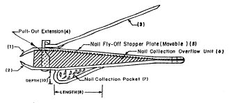
The Figure 1 shows the front coross-sectional view of nail clipper.
The Figure 2 shows the back coross-sectional view of nail clipper.
The Figure 3 shows the plan coross-sectional view of nail clipper.


Detailed Description of the Preferred Embodiment:

The Figure 1 illustrated an improved nail clipper assembly wllich
includes the movable plate(5) to prevent nail clipping to fly-off or
scattered during nail clipping operation. This plate(5) snap against the
upper(1) and lower(2) jaw plates of the clipper. It provides additional
storage(6) between two jaw plates for storing nail clippings. This

(4)

Z040~7

plate(5) does not obstruct the movement of upper ~aw plate(1) during
clipping operation. The nail collection pocket(7) ls attached to the
lower ~aw ~la~e(2). The shape of this pocket is des~gned as shown to
prevent the clippings to be struck in the corners of this pocket. The
smoo~h corners in this pocket facilitate in emptying the pocket without
any clipping left behind in the clipping pocket(7). The length(8),
width(9) and depth(10) of the nail collection pocket(7) varies with the
size of clipper. The Figure 2 shows the another important feature of the
present i~vention and that is front side plate(11) attached to the lower
~aw plate(2). This plate covers the opening between the jaw plates and
does not obstruct the movement of upper ~aw plate(1) during clipping
operation. The clipping as they exit the upper(1~ and lower(2) ~aw
plates, they either strike front(ll) or back(5) side plates and get
stored in the storage(6) provided between two ~aw plates or fall down in
the nail collection pocket(7). The nail collection pocket can be filled
by tilting the nail clipper down to get the clippings lying at the back
of storage(6) area between the jaw plates or tilting the clipper up to
get the clippings from the ront storage(6) area between the jaw plates.
The nail collection pocket(7) and the storage area(6) between the jaw
plates could be emptied by pulling out the back plate(5) and by shaking
out the clippings in the disposal basket and snapping back the plate(5)
for future use. The Figure 3 shows that the cross-sectional plan view of
the nail clipper. The shape of the nail collection pocket(7) is designed
in a well rounded manner so that the it is easy to e~pty the pocket~7)
without leaving any clippings in there. The nail collection pockett7)

( 5 )


Z040117

could be welded to the lower ~aw(2) or could be formed as one unified
unit. The size of pocket (7) varies with the size of nail clipper. The
material used for this nail clipper could be any single metal or an
alloy consisting of one or more metal elements. Although the present
invention has been described in terms of the presently preferred
embodiment, it is to be understood that such disclosure is not to be
lnterpreted as l~miting. Varlous alterations and mod~fications wlll no
so doubt become apparent to those qualified and skilled in the art afterhaving read the above disclosure. Accordingly, it is intended that the
appended claims be interpreted as covering all alterations and
modifications as fall within the true spirit and scope of the invention.

Representative Drawing
A single figure which represents the drawing illustrating the invention.
Administrative Status

For a clearer understanding of the status of the application/patent presented on this page, the site Disclaimer , as well as the definitions for Patent , Administrative Status , Maintenance Fee  and Payment History  should be consulted.

Administrative Status

Title Date
Forecasted Issue Date Unavailable
(22) Filed 1991-04-09
(41) Open to Public Inspection 1992-10-10
Dead Application 1999-04-09

Abandonment History

Abandonment Date Reason Reinstatement Date
1998-04-09 FAILURE TO REQUEST EXAMINATION
1998-04-09 FAILURE TO PAY APPLICATION MAINTENANCE FEE

Payment History

Fee Type Anniversary Year Due Date Amount Paid Paid Date
Application Fee $0.00 1991-04-09
Maintenance Fee - Application - New Act 2 1993-04-09 $50.00 1992-07-14
Maintenance Fee - Application - New Act 3 1994-04-11 $50.00 1993-05-12
Maintenance Fee - Application - New Act 4 1995-04-10 $50.00 1994-04-08
Maintenance Fee - Application - New Act 5 1996-04-09 $75.00 1995-09-13
Maintenance Fee - Application - New Act 6 1997-04-09 $75.00 1997-03-25
Owners on Record

Note: Records showing the ownership history in alphabetical order.

Current Owners on Record
KHANNA, VIR K.
Past Owners on Record
None
Past Owners that do not appear in the "Owners on Record" listing will appear in other documentation within the application.
Documents

To view selected files, please enter reCAPTCHA code :


To view images, click a link in the Document Description column. To download the documents, select one or more checkboxes in the first column and then click the "Download Selected in PDF format (Zip Archive)" or the "Download Selected as Single PDF" button.

List of published and non-published patent-specific documents on the CPD .

If you have any difficulty accessing content, you can call the Client Service Centre at 1-866-997-1936 or send them an e-mail at CIPO Client Service Centre.


Document
Description 
Date
(yyyy-mm-dd) 
Number of pages   Size of Image (KB) 
Representative Drawing 1999-04-14 1 8
Cover Page 1992-10-10 1 11
Abstract 1992-10-10 1 10
Claims 1992-10-10 1 18
Drawings 1992-10-10 1 24
Description 1992-10-10 5 125
Fees 1997-03-25 2 102
Fees 1995-09-13 1 38
Fees 1994-04-08 1 95
Correspondence 1993-06-23 3 63
Fees 1993-05-12 1 94
Fees 1992-07-14 1 70