Sélection de la langue

Search

Sommaire du brevet 2040117 

Énoncé de désistement de responsabilité concernant l'information provenant de tiers

Une partie des informations de ce site Web a été fournie par des sources externes. Le gouvernement du Canada n'assume aucune responsabilité concernant la précision, l'actualité ou la fiabilité des informations fournies par les sources externes. Les utilisateurs qui désirent employer cette information devraient consulter directement la source des informations. Le contenu fourni par les sources externes n'est pas assujetti aux exigences sur les langues officielles, la protection des renseignements personnels et l'accessibilité.

Disponibilité de l'Abrégé et des Revendications

L'apparition de différences dans le texte et l'image des Revendications et de l'Abrégé dépend du moment auquel le document est publié. Les textes des Revendications et de l'Abrégé sont affichés :

  • lorsque la demande peut être examinée par le public;
  • lorsque le brevet est émis (délivrance).
(12) Demande de brevet: (11) CA 2040117
(54) Titre français: APPAREIL COUPE-ONGLES
(54) Titre anglais: NAIL CLIPPER UNIT
Statut: Morte
Données bibliographiques
Abrégés

Abrégé anglais


Abstract:

The conventional nail clipper is the one most commonly known. It is
common experience of many who use conventional nail clipper to have nail
clippings scattering all over as fingernails and toenails are being
clipped. The present invention is designed to prevent scattering and
also to provide storage within the clipper to hold back clippings, which
can be disposed off at convenient time and at appropriate place.

Revendications

Note : Les revendications sont présentées dans la langue officielle dans laquelle elles ont été soumises.


CLAIMS:
1. The front side plate(11) shown in the Figure 1 is welded or formed
as one unit to the lower jaw plate(2) of nail clipper.

2. The back snap-on plate(5) to provide additional storage(6) for nail
clippings between the upper(1) and lower(2) jaws of nail clipper.

3. The snap-on plate(5) could be fixed or movable to empty the nail
collection pocket(7) and the storage area(6) between the upper (1)
and lower(2) jaws of nail clipper.

4. The nail collection pocket(7) is cut in a elliptical or other
circular or curved or any other practical shape in the lower jaw
plate(2) of the nail clipper to facilitate easy storage and emptying
operation.

5. The nail collection pocket is formed as one unit or it could be
welded to the lower jaw plate(2) in the shape as shown in the
Figures 1 and 2 with curved corners to facilitate easy storage and
emptying operation.

Description

Note : Les descriptions sont présentées dans la langue officielle dans laquelle elles ont été soumises.

( I )


2040117

~ackground of the Invention:


1. Field of the Invention:


Thls invention is related to na;l clipper and most particularly to
an improved and simplified nail clipper unit which has arrangement
bUilt in the unit to catch nail clippings and store them for disposal
at convenient time and appropriate place.


2. Description of the Prior Art:


The conventlonal nail clipper is the one most commonly known in the
prior art. There are other patent sighted with assembly to hold nail

clippings but those are not commercialized yet and are not available
in the public because of their complex operation and outlook. It is
common experience of many who use conventional nail clipper to have
nail cllppings scattering all over as fingernails or toenails are
clipped. The inventor is unaware of any previous design or prod~ct
which look similar to given in this invention which will prevent nail
clipping from scattering and store them for disposal at convenient

time and appropriate place.


Summary of the Present Invention:


It is an objective of the present invention to provide an improved and

(2)


2040~17

slmplified version of nail clipper which will prevent the scattering of
nail clippings during the operation of the nail clipper.

It is a further object to provide improved and simpler storage mechanism
until approprlate d~sposal ls convenlent.

Briefly, in a preferred embodiment, the present invention includes on
movable plate on rlght hand side of the cllpper. It snaps against the
lower and upper jaws of the clipper on the side and covers the opening
between the iaws and thUS prov~d~ng additlonal storage area for nail
clipping. The snap-on plate prevent the nail clippings to fly-off or
scatter or escape from that side. This plate can be pulled out to empty
the nail collection pocket and additional storage area containing nail
clippings. On left hand side of the clipper, the opening is covered by
rolled over plate which is attached to the lower ~aw plate. This plate
also prevent nail clippings to scatter, or fly-off during clipping
operation. There is storage provided in the lower jaw plate of the nail
clipper to store the clippings. The length and depth of the nail
collection pocket varies with the size of nail clipper.

An advantage of a nail clipper assembly of the present invention is that
the scattering of the na;l cl;ppings during ;ts operation is prevented.

A further advantage is that the operation of this nail clipper is very
simple.

(3)

2040117


A further advantage of the present invention is that it provides storage
and utilizes the unused space between two jaw plates of nail clipper as
additional storage for nail clippings.

These and o~her ob~ects and advantages of the present invention will no
doubt obvious to those of ordinary skills in the art after having read
the following detailed descriptions of the preferred embodiment which is
illustrated in the var;ous drawing figures.


T~E DRAUINGS:

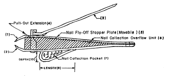
The Figure 1 shows the front coross-sectional view of nail clipper.
The Figure 2 shows the back coross-sectional view of nail clipper.
The Figure 3 shows the plan coross-sectional view of nail clipper.


Detailed Description of the Preferred Embodiment:

The Figure 1 illustrated an improved nail clipper assembly wllich
includes the movable plate(5) to prevent nail clipping to fly-off or
scattered during nail clipping operation. This plate(5) snap against the
upper(1) and lower(2) jaw plates of the clipper. It provides additional
storage(6) between two jaw plates for storing nail clippings. This

(4)

Z040~7

plate(5) does not obstruct the movement of upper ~aw plate(1) during
clipping operation. The nail collection pocket(7) ls attached to the
lower ~aw ~la~e(2). The shape of this pocket is des~gned as shown to
prevent the clippings to be struck in the corners of this pocket. The
smoo~h corners in this pocket facilitate in emptying the pocket without
any clipping left behind in the clipping pocket(7). The length(8),
width(9) and depth(10) of the nail collection pocket(7) varies with the
size of clipper. The Figure 2 shows the another important feature of the
present i~vention and that is front side plate(11) attached to the lower
~aw plate(2). This plate covers the opening between the jaw plates and
does not obstruct the movement of upper ~aw plate(1) during clipping
operation. The clipping as they exit the upper(1~ and lower(2) ~aw
plates, they either strike front(ll) or back(5) side plates and get
stored in the storage(6) provided between two ~aw plates or fall down in
the nail collection pocket(7). The nail collection pocket can be filled
by tilting the nail clipper down to get the clippings lying at the back
of storage(6) area between the jaw plates or tilting the clipper up to
get the clippings from the ront storage(6) area between the jaw plates.
The nail collection pocket(7) and the storage area(6) between the jaw
plates could be emptied by pulling out the back plate(5) and by shaking
out the clippings in the disposal basket and snapping back the plate(5)
for future use. The Figure 3 shows that the cross-sectional plan view of
the nail clipper. The shape of the nail collection pocket(7) is designed
in a well rounded manner so that the it is easy to e~pty the pocket~7)
without leaving any clippings in there. The nail collection pockett7)

( 5 )


Z040117

could be welded to the lower ~aw(2) or could be formed as one unified
unit. The size of pocket (7) varies with the size of nail clipper. The
material used for this nail clipper could be any single metal or an
alloy consisting of one or more metal elements. Although the present
invention has been described in terms of the presently preferred
embodiment, it is to be understood that such disclosure is not to be
lnterpreted as l~miting. Varlous alterations and mod~fications wlll no
so doubt become apparent to those qualified and skilled in the art afterhaving read the above disclosure. Accordingly, it is intended that the
appended claims be interpreted as covering all alterations and
modifications as fall within the true spirit and scope of the invention.

Dessin représentatif
Une figure unique qui représente un dessin illustrant l'invention.
États administratifs

Pour une meilleure compréhension de l'état de la demande ou brevet qui figure sur cette page, la rubrique Mise en garde , et les descriptions de Brevet , États administratifs , Taxes périodiques et Historique des paiements devraient être consultées.

États administratifs

Titre Date
Date de délivrance prévu Non disponible
(22) Dépôt 1991-04-09
(41) Mise à la disponibilité du public 1992-10-10
Demande morte 1999-04-09

Historique d'abandonnement

Date d'abandonnement Raison Reinstatement Date
1998-04-09 Absence de requête d'examen
1998-04-09 Taxe périodique sur la demande impayée

Historique des paiements

Type de taxes Anniversaire Échéance Montant payé Date payée
Le dépôt d'une demande de brevet 0,00 $ 1991-04-09
Taxe de maintien en état - Demande - nouvelle loi 2 1993-04-09 50,00 $ 1992-07-14
Taxe de maintien en état - Demande - nouvelle loi 3 1994-04-11 50,00 $ 1993-05-12
Taxe de maintien en état - Demande - nouvelle loi 4 1995-04-10 50,00 $ 1994-04-08
Taxe de maintien en état - Demande - nouvelle loi 5 1996-04-09 75,00 $ 1995-09-13
Taxe de maintien en état - Demande - nouvelle loi 6 1997-04-09 75,00 $ 1997-03-25
Titulaires au dossier

Les titulaires actuels et antérieures au dossier sont affichés en ordre alphabétique.

Titulaires actuels au dossier
KHANNA, VIR K.
Titulaires antérieures au dossier
S.O.
Les propriétaires antérieurs qui ne figurent pas dans la liste des « Propriétaires au dossier » apparaîtront dans d'autres documents au dossier.
Documents

Pour visionner les fichiers sélectionnés, entrer le code reCAPTCHA :


Pour visualiser une image, cliquer sur un lien dans la colonne description du document. Pour télécharger l'image (les images), cliquer l'une ou plusieurs cases à cocher dans la première colonne et ensuite cliquer sur le bouton "Télécharger sélection en format PDF (archive Zip)" ou le bouton "Télécharger sélection (en un fichier PDF fusionné)".

Liste des documents de brevet publiés et non publiés sur la BDBC .

Si vous avez des difficultés à accéder au contenu, veuillez communiquer avec le Centre de services à la clientèle au 1-866-997-1936, ou envoyer un courriel au Centre de service à la clientèle de l'OPIC.


Description du
Document 
Date
(yyyy-mm-dd) 
Nombre de pages   Taille de l'image (Ko) 
Dessins représentatifs 1999-04-14 1 8
Page couverture 1992-10-10 1 11
Abrégé 1992-10-10 1 10
Revendications 1992-10-10 1 18
Dessins 1992-10-10 1 24
Description 1992-10-10 5 125
Taxes 1997-03-25 2 102
Taxes 1995-09-13 1 38
Taxes 1994-04-08 1 95
Correspondance 1993-06-23 3 63
Taxes 1993-05-12 1 94
Taxes 1992-07-14 1 70