Language selection

Search

Patent 2040568 Summary

Third-party information liability

Some of the information on this Web page has been provided by external sources. The Government of Canada is not responsible for the accuracy, reliability or currency of the information supplied by external sources. Users wishing to rely upon this information should consult directly with the source of the information. Content provided by external sources is not subject to official languages, privacy and accessibility requirements.

Claims and Abstract availability

Any discrepancies in the text and image of the Claims and Abstract are due to differing posting times. Text of the Claims and Abstract are posted:

  • At the time the application is open to public inspection;
  • At the time of issue of the patent (grant).
(12) Patent: (11) CA 2040568
(54) English Title: DIAPHRAGM ACTUATED VALVE ASSEMBLY
(54) French Title: SOUPAPE A MEMBRANE
Status: Deemed expired
Bibliographic Data
(52) Canadian Patent Classification (CPC):
  • 137/39.1
(51) International Patent Classification (IPC):
  • F16K 31/126 (2006.01)
  • F16K 31/40 (2006.01)
(72) Inventors :
  • DONNER, RICHARD A. (United States of America)
(73) Owners :
  • EATON CORPORATION (United States of America)
(71) Applicants :
(74) Agent: BORDEN LADNER GERVAIS LLP
(74) Associate agent:
(45) Issued: 1995-05-09
(22) Filed Date: 1991-04-16
(41) Open to Public Inspection: 1991-10-26
Examination requested: 1993-03-25
Availability of licence: N/A
(25) Language of filing: English

Patent Cooperation Treaty (PCT): No

(30) Application Priority Data:
Application No. Country/Territory Date
516,494 United States of America 1990-04-25

Abstracts

English Abstract


A pilot operated, diaphragm actuated fluid valve
assembly having an annular main valve seat with a tapered
annular surface disposed therearound. A movable diaphragm
has a generally flat central main valving surface thereon
and an integrally formed annular wiper extending outwardly
therefrom. The annular wiper contacts the tapered annular
surface a relatively small distance before the main
valving surface contacts the main valve seat.


Claims

Note: Claims are shown in the official language in which they were submitted.

THE EMBODIMENTS OF THE INVENTION IN WHICH AN EXCLUSIVE
PROPERTY OR PRIVILEGE IS CLAIMED ARE DEFINED AS FOLLOWS:

1. An improved valve assembly for a valve of the type
having a pressure responsive diaphragm:
(a) body structure defining a valve outlet port with an
annular valve seating surface thereabout and having
a second surface radially outwardly of and
intersecting said annular seating surface;
(b) a flexible diaphragm having the periphery thereof
sealingly secured to said body structure and a
central portion movable between a position
contacting and a position spaced from said annular
seating surface;
(c) annular flexible wiper means attached to said
diaphragm and extending therefrom in a direction
toward said second annular surface, said wiper means
configured such that upon movement of said diaphragm
intermediate portion said wiper means contacts said
second annular surface in fluid pressure sealing
arrangement before said diaphragm intermediate
portion closes on said annular seating surface said
wiper means thereby providing redundant sealing with
said annular sealing surface; and,
(d) means operative to move said diaphragm valving
surface between said open and closed position, and
forming an annular space as said wiper means engages
said second annular surface for trapping foreign
particles continuously as said diaphragm
intermediate portion contacts said annular seating
surface which prevents such particles from being
trapped on said annular seating surface which might
prevent said diaphragm intermediate portion from
closing.

2. The valve assembly defined in claim 1, wherein said
wiper means slidably contacts said second annular surface
and is deformed radially outwardly as said intermediate
portion closes on said annular seating surfaces.


3. A valve assembly of the type employing a pressure
responsive member movable for controlling flow to an outlet:
(a) body structure defining a valving chamber adapted
for being supplied with a source of fluid, said
valving chamber having an annular valve seat for
controlling flow to an outlet communicating with
said valving chamber;
(b) a flexible diaphragm having the periphery thereof
sealingly attached to said body structure and
thereby forming a movable wall portion for said
valving chamber;
(c) a valving surface provided on said diaphragm, for
movement between a closed position contacting said
annular seating surface for blocking flow to said
outlet and an open position permitting flow to said
outlet;
(d) an annular secondary surface disposed radially
outwardly of said annular valve seat; and,
(e) annular wiper means extending from said diaphragm
and surrounding said diaphragm valving surface, said
wiper means operative upon movement of said
diaphragm to contact said annular secondary surface
before said valving surface contacts said annular
valve seat and, seals thereabout said wiper means
resiliently deformed by continued movement of said
valving surface to the closed position, said wiper
thereby providing redundant sealing with said
diaphragm valving surface, and forming an annular
space as said wiper means engages said annular
secondary surface for trapping foreign particles
continuously as said diaphragm valving surface
contacts said annular valve seat which prevents such
particles from being trapped on said annular valve
seat which particles might prevent said diaphragm
valving surface from closing.


Description

Note: Descriptions are shown in the official language in which they were submitted.


- ~ 2040568

DIAPR~AG~ ACTUATED VALVE ~ FMRT.y


BACKGROUND OF THE INVENTION

The present invention relates to fluid valves of the
pilot operated type having a diaphragm actuated main valve
and particularly to valves of the type having the pilot
valve member electrically energized. Valves of this type
05 are commonly employed for controlling water inlet flow to
household appliances such as washing machines and dish
washers.
Typically, in appliance water inlet valves, an
electromagnetic actuator such as a solenoid coil moves the
pilot valve member to permit water at line pressure in a
pilot chamber to discharge to the outlet thereby creating
a pressure differential across a flexible diaphragm having
the central portion thereof acting as a main valve.
Forces of the pressure differential acting across the
surfaces of the diaphragm then move the diaphragm to open
the main valve permitting a larger flow to the outlet.
Such solenoid operated pilot valves draw a very low
current and therefore can be energized and deenergized by
a set of electrical contacts operated by a small timing
motor driven programmer.
Valves of this type are relatively low in manufacturing
costs and are readily manufactured in very high volume
mass production for the residential appliance industry.
In designing pilot operated diaphragm actuated valves
for appliance water inlet, problems have been encountered
with leakage across the main valve seating surface often
caused by the trapping of foreign particles in the water
supply on the main valve seat thereby preventing the valve
from closing altogether.
Thus it has been desired to find a way or means of
proving the reliability of closing of a pilot operated
diaphragm actuated valve assembly without requiring
complete redesign and retooling of the valve. -

90--CON--110 (AP) 0829K
Page 2 2040568

SUMMARY OF THE INVENTION

The present invention provides a pilot operated
diaphragm actuated fluid valve of the type having the
central portion of the diaphragm contacting an annular
valve seat for closing the main valve, with a pilot valve
05 orifice disposed centrally of the annular main valve
seat. The peripheral portions of the diaphragm are
fle~ible to permit the central flat portion to be moved
between an open position spaced from and a closed position
contacting the annular valve seat. = -
The annular valve seat has disposed therearound a
secondary annular preferably conically tapered surfac~
which is contacted by an annular flexible wiper formed
integrally with and extending outwardly from the main
valve seat on the diaphragm. As the main valve nears the
closed position, the annular wiper makes sliding contact
with the secondary surface providing sealing and
preferably wiping of foreign material from the valve seat
conically tapered region. The annular wiper is maintained
in a stretched and sealed condition against the tapered
surface thereby providing redundant sealing for the main
valve.
The present invention thus provides an improved pilot
operated diaphragm actuated valve assembly having a
tapered surface surrounding the annular valve seat with
an annular wiper slidably contacting the tapered surface
to provide redundant sealing immediately prior to closi~
of the main valve.


A

Page 2a 2040568

Specifically, and in accordance with this invention there
is provided an improved valve assembly for a valve of the
type having a pressure responsive diaphragm:
(a) body structure defining a valve outlet port with an
annular valve seating surface thereabout and having
a second surface radially outwardly of and
intersecting said annular seating surface;
(b) a flexible diaphragm having the periphery thereof
sealingly secured to said body structure and a
central portion movable between a position
contacting and a position spaced from said annular
seating surface;
(c) annular flexible wiper means attached to said
diaphragm and exten~; ng therefrom in a direction
toward said second annular surface, said wiper means
configured such that upon movement of said diaphragm
intermediate portion said wiper means contacts said
second annular surface in fluid pressure sealing
arrangement before said diaphragm intermediate
portion closes on said annular seating surface said
wiper means thereby providing re~lln~Ant sealing with
said annular sealing surface; and,
(d) means operative to move said diaphragm valving
surface between said open and closed position, and
forming an annular space as said wiper means engages
said second annular surface for trapping foreign
particles continuously as said diaphragm
intermediate portion contacts said annular seating
surface which prevents such particles from being
trapped on said annular seating surface which might
prevent said diaphragm intermediate portion from
closing.
BRIEF DESCRIPTION OF THE DRAWINGS
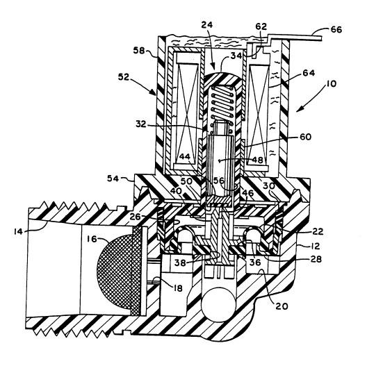
FIGURE 1 is a cross-sectional view of a valve assembly
employing the present invention; and,
FIGURE 2 is an enlarged view of a portion of Figure 1.

90-CON-110 (AP) 0829K
Page 3
- 2040568

SUMMARY OF T~ INVENTION

The valve assembly of the present invention is
indicated generally at lO having a body 12 formed of
suitable plastic material with an inlet 14 formed therein
with a filter screen 16. The inlet 14 communicates
05 through passage 18 with a main valving chamber 20. The
valving chamber 20 is closed by a flexible diaphragm 22
having the periphery thereof sealed about the rim of a
bell-shaped armature guide member indicated generally at
24, with the diaphragm sealed about the rim enlarged
diameter portion 26 thereof. The rim of the diaphragm is
retained on the rim of the enlarged diameter portion 26 of
the armature guide by a suitable annular band 28 having a
generally U-shaped cross section. The band 28 and the
enlarged portion 26 of the armature are sealed in the
valving cavity 20 by a suitable sealing ring 30.
The upper portion of armature guide 24 comprises a
reduced diameter hollow tubular portion 32 having the
upper end 34 thereof closed.
The flexible diaphragm 22 has a thickened center
portion 36 which has a generally flat undersurface 37 and
a central aperture 38 formed therethrough. A rigid insert
40 is received through aperture 38 which insert has a
pilot valve seat 42 provided on the upper end thereof with
a central pilot passage 46 provided therethrough.
A movable valve member is slidably received in the
hollow interior of the upper portion 32 of the armature
guide 24 and comprises ferromagnetic armature 48 having an
elastomeric pad 50 provided in the lower end thereof which
contacts the pilot valve seat 44.
The armature guide 24 is retained in the body by an
annular cup member indicated generally at 52 which has a
thickened closed end portion having a radially outwardly
extending flange 54 which is sealed over the body and

90-CON-110 (AP) 0829K
Page 4 2040568
-

retained thereon by suitable weldment. The upper tubular
portion 32 of the armature guide extends through an
aperture 56 provided in the cup member.
The upper cylindrical wall portion 58 of the cup 52
05 has received therein tubular ferromagnetic pole pieces 60,
62, which pole pieces are separated by an axial air gap.
A suitable electrical solenoid coil 64 is received
thereover and is potted in the cup 52. Suitable
electrical terminals such as terminal strip 64 extend from
coil 64 outwardly of the cup for electrical connection
thereto.
Referring particularly to Figure 2, the valving cavity
20 has formed therein an annular main valve seat 68 which
surrounds and communicates with outlet passage 70 which is
open to the valve outlet 72.
The pilot passage 46 of insert 40 also communicates
with passage 70 through the diaphragm central portion 36.
The main valve valve seat 68 is contacted by the
undersurface 37 of the valving portion 96 of the diaphragm
when the valve is in the closed position as shown in the
drawings.
It will be understood that the main valve seat 37 is
moved upwardly away from seat 68 when the valve is in the
open position.
The main valve seat 68 is surrounded radially
outwardly thereof by a secondary preferably tapered
surface 74 extending downwardly therefrom.
An annular wiper portion 76 is formed integrally with
the undesurface 37 of the diaphragm and the wiper 76 has
the rim thereof sized and configured to contact the
tapered surface 74 prior to the closing of the main valve
member against seat 68 such that the wiper 76 seals
preferably slidably along surface 74 and is stretched
outwardly as the main valving surface 37 seats against

90-CON-110 (AP) 0829K
Page 5
2040568

main valve seat 68. The wiper 76 thus provides a
redundant sealing of the main valve. The region between
the wiper 76 and the main valve seat 68, denoted by
reference numeral 78, provides a suitable annular space to
05 trap foreign particles which may have passed through the
screen 16 and which might otherwise prevent the main valve
seat from being closed.
The wiper 76 thus enables an existing valve design to
be modified by changing only the taper of the conical
surface 74 and the addition of the wiper 76 to the
fle~ible diaphragm to provide for improved redundant
sealing of the main valve and provides protection against
lodgement of foreign particles which might prevent the
valve from fully closing.
Although the invention has hereinabove been described
with respect to the illustrated embodiments, it will be
understood that the invention is limited only by the
following claims:

Representative Drawing
A single figure which represents the drawing illustrating the invention.
Administrative Status

For a clearer understanding of the status of the application/patent presented on this page, the site Disclaimer , as well as the definitions for Patent , Administrative Status , Maintenance Fee  and Payment History  should be consulted.

Administrative Status

Title Date
Forecasted Issue Date 1995-05-09
(22) Filed 1991-04-16
(41) Open to Public Inspection 1991-10-26
Examination Requested 1993-03-25
(45) Issued 1995-05-09
Deemed Expired 1997-04-16

Abandonment History

There is no abandonment history.

Payment History

Fee Type Anniversary Year Due Date Amount Paid Paid Date
Application Fee $0.00 1991-04-16
Registration of a document - section 124 $0.00 1991-10-22
Maintenance Fee - Application - New Act 2 1993-04-16 $100.00 1993-02-11
Maintenance Fee - Application - New Act 3 1994-04-18 $100.00 1994-03-23
Maintenance Fee - Application - New Act 4 1995-04-17 $100.00 1995-03-21
Owners on Record

Note: Records showing the ownership history in alphabetical order.

Current Owners on Record
EATON CORPORATION
Past Owners on Record
DONNER, RICHARD A.
Past Owners that do not appear in the "Owners on Record" listing will appear in other documentation within the application.
Documents

To view selected files, please enter reCAPTCHA code :


To view images, click a link in the Document Description column. To download the documents, select one or more checkboxes in the first column and then click the "Download Selected in PDF format (Zip Archive)" or the "Download Selected as Single PDF" button.

List of published and non-published patent-specific documents on the CPD .

If you have any difficulty accessing content, you can call the Client Service Centre at 1-866-997-1936 or send them an e-mail at CIPO Client Service Centre.


Document
Description 
Date
(yyyy-mm-dd) 
Number of pages   Size of Image (KB) 
Abstract 1995-05-09 1 14
Drawings 1995-05-09 2 56
Cover Page 1995-05-09 1 16
Claims 1995-05-09 2 84
Description 1995-05-09 6 237
Representative Drawing 1999-08-19 1 33
Prosecution Correspondence 1993-03-25 1 22
PCT Correspondence 1995-02-27 1 29
Prosecution Correspondence 1994-08-09 2 42
Office Letter 1993-04-14 1 68
Examiner Requisition 1994-04-22 1 58
Fees 1995-03-21 1 74
Fees 1994-03-23 1 62
Fees 1993-02-11 1 64