Sélection de la langue

Search

Sommaire du brevet 2040568 

Énoncé de désistement de responsabilité concernant l'information provenant de tiers

Une partie des informations de ce site Web a été fournie par des sources externes. Le gouvernement du Canada n'assume aucune responsabilité concernant la précision, l'actualité ou la fiabilité des informations fournies par les sources externes. Les utilisateurs qui désirent employer cette information devraient consulter directement la source des informations. Le contenu fourni par les sources externes n'est pas assujetti aux exigences sur les langues officielles, la protection des renseignements personnels et l'accessibilité.

Disponibilité de l'Abrégé et des Revendications

L'apparition de différences dans le texte et l'image des Revendications et de l'Abrégé dépend du moment auquel le document est publié. Les textes des Revendications et de l'Abrégé sont affichés :

  • lorsque la demande peut être examinée par le public;
  • lorsque le brevet est émis (délivrance).
(12) Brevet: (11) CA 2040568
(54) Titre français: SOUPAPE A MEMBRANE
(54) Titre anglais: DIAPHRAGM ACTUATED VALVE ASSEMBLY
Statut: Réputé périmé
Données bibliographiques
(52) Classification canadienne des brevets (CCB):
  • 137/39.1
(51) Classification internationale des brevets (CIB):
  • F16K 31/126 (2006.01)
  • F16K 31/40 (2006.01)
(72) Inventeurs :
  • DONNER, RICHARD A. (Etats-Unis d'Amérique)
(73) Titulaires :
  • EATON CORPORATION (Etats-Unis d'Amérique)
(71) Demandeurs :
(74) Agent: BORDEN LADNER GERVAIS LLP
(74) Co-agent:
(45) Délivré: 1995-05-09
(22) Date de dépôt: 1991-04-16
(41) Mise à la disponibilité du public: 1991-10-26
Requête d'examen: 1993-03-25
Licence disponible: S.O.
(25) Langue des documents déposés: Anglais

Traité de coopération en matière de brevets (PCT): Non

(30) Données de priorité de la demande:
Numéro de la demande Pays / territoire Date
516,494 Etats-Unis d'Amérique 1990-04-25

Abrégés

Abrégé anglais


A pilot operated, diaphragm actuated fluid valve
assembly having an annular main valve seat with a tapered
annular surface disposed therearound. A movable diaphragm
has a generally flat central main valving surface thereon
and an integrally formed annular wiper extending outwardly
therefrom. The annular wiper contacts the tapered annular
surface a relatively small distance before the main
valving surface contacts the main valve seat.

Revendications

Note : Les revendications sont présentées dans la langue officielle dans laquelle elles ont été soumises.


THE EMBODIMENTS OF THE INVENTION IN WHICH AN EXCLUSIVE
PROPERTY OR PRIVILEGE IS CLAIMED ARE DEFINED AS FOLLOWS:

1. An improved valve assembly for a valve of the type
having a pressure responsive diaphragm:
(a) body structure defining a valve outlet port with an
annular valve seating surface thereabout and having
a second surface radially outwardly of and
intersecting said annular seating surface;
(b) a flexible diaphragm having the periphery thereof
sealingly secured to said body structure and a
central portion movable between a position
contacting and a position spaced from said annular
seating surface;
(c) annular flexible wiper means attached to said
diaphragm and extending therefrom in a direction
toward said second annular surface, said wiper means
configured such that upon movement of said diaphragm
intermediate portion said wiper means contacts said
second annular surface in fluid pressure sealing
arrangement before said diaphragm intermediate
portion closes on said annular seating surface said
wiper means thereby providing redundant sealing with
said annular sealing surface; and,
(d) means operative to move said diaphragm valving
surface between said open and closed position, and
forming an annular space as said wiper means engages
said second annular surface for trapping foreign
particles continuously as said diaphragm
intermediate portion contacts said annular seating
surface which prevents such particles from being
trapped on said annular seating surface which might
prevent said diaphragm intermediate portion from
closing.

2. The valve assembly defined in claim 1, wherein said
wiper means slidably contacts said second annular surface
and is deformed radially outwardly as said intermediate
portion closes on said annular seating surfaces.


3. A valve assembly of the type employing a pressure
responsive member movable for controlling flow to an outlet:
(a) body structure defining a valving chamber adapted
for being supplied with a source of fluid, said
valving chamber having an annular valve seat for
controlling flow to an outlet communicating with
said valving chamber;
(b) a flexible diaphragm having the periphery thereof
sealingly attached to said body structure and
thereby forming a movable wall portion for said
valving chamber;
(c) a valving surface provided on said diaphragm, for
movement between a closed position contacting said
annular seating surface for blocking flow to said
outlet and an open position permitting flow to said
outlet;
(d) an annular secondary surface disposed radially
outwardly of said annular valve seat; and,
(e) annular wiper means extending from said diaphragm
and surrounding said diaphragm valving surface, said
wiper means operative upon movement of said
diaphragm to contact said annular secondary surface
before said valving surface contacts said annular
valve seat and, seals thereabout said wiper means
resiliently deformed by continued movement of said
valving surface to the closed position, said wiper
thereby providing redundant sealing with said
diaphragm valving surface, and forming an annular
space as said wiper means engages said annular
secondary surface for trapping foreign particles
continuously as said diaphragm valving surface
contacts said annular valve seat which prevents such
particles from being trapped on said annular valve
seat which particles might prevent said diaphragm
valving surface from closing.


Description

Note : Les descriptions sont présentées dans la langue officielle dans laquelle elles ont été soumises.

- ~ 2040568

DIAPR~AG~ ACTUATED VALVE ~ FMRT.y


BACKGROUND OF THE INVENTION

The present invention relates to fluid valves of the
pilot operated type having a diaphragm actuated main valve
and particularly to valves of the type having the pilot
valve member electrically energized. Valves of this type
05 are commonly employed for controlling water inlet flow to
household appliances such as washing machines and dish
washers.
Typically, in appliance water inlet valves, an
electromagnetic actuator such as a solenoid coil moves the
pilot valve member to permit water at line pressure in a
pilot chamber to discharge to the outlet thereby creating
a pressure differential across a flexible diaphragm having
the central portion thereof acting as a main valve.
Forces of the pressure differential acting across the
surfaces of the diaphragm then move the diaphragm to open
the main valve permitting a larger flow to the outlet.
Such solenoid operated pilot valves draw a very low
current and therefore can be energized and deenergized by
a set of electrical contacts operated by a small timing
motor driven programmer.
Valves of this type are relatively low in manufacturing
costs and are readily manufactured in very high volume
mass production for the residential appliance industry.
In designing pilot operated diaphragm actuated valves
for appliance water inlet, problems have been encountered
with leakage across the main valve seating surface often
caused by the trapping of foreign particles in the water
supply on the main valve seat thereby preventing the valve
from closing altogether.
Thus it has been desired to find a way or means of
proving the reliability of closing of a pilot operated
diaphragm actuated valve assembly without requiring
complete redesign and retooling of the valve. -

90--CON--110 (AP) 0829K
Page 2 2040568

SUMMARY OF THE INVENTION

The present invention provides a pilot operated
diaphragm actuated fluid valve of the type having the
central portion of the diaphragm contacting an annular
valve seat for closing the main valve, with a pilot valve
05 orifice disposed centrally of the annular main valve
seat. The peripheral portions of the diaphragm are
fle~ible to permit the central flat portion to be moved
between an open position spaced from and a closed position
contacting the annular valve seat. = -
The annular valve seat has disposed therearound a
secondary annular preferably conically tapered surfac~
which is contacted by an annular flexible wiper formed
integrally with and extending outwardly from the main
valve seat on the diaphragm. As the main valve nears the
closed position, the annular wiper makes sliding contact
with the secondary surface providing sealing and
preferably wiping of foreign material from the valve seat
conically tapered region. The annular wiper is maintained
in a stretched and sealed condition against the tapered
surface thereby providing redundant sealing for the main
valve.
The present invention thus provides an improved pilot
operated diaphragm actuated valve assembly having a
tapered surface surrounding the annular valve seat with
an annular wiper slidably contacting the tapered surface
to provide redundant sealing immediately prior to closi~
of the main valve.


A

Page 2a 2040568

Specifically, and in accordance with this invention there
is provided an improved valve assembly for a valve of the
type having a pressure responsive diaphragm:
(a) body structure defining a valve outlet port with an
annular valve seating surface thereabout and having
a second surface radially outwardly of and
intersecting said annular seating surface;
(b) a flexible diaphragm having the periphery thereof
sealingly secured to said body structure and a
central portion movable between a position
contacting and a position spaced from said annular
seating surface;
(c) annular flexible wiper means attached to said
diaphragm and exten~; ng therefrom in a direction
toward said second annular surface, said wiper means
configured such that upon movement of said diaphragm
intermediate portion said wiper means contacts said
second annular surface in fluid pressure sealing
arrangement before said diaphragm intermediate
portion closes on said annular seating surface said
wiper means thereby providing re~lln~Ant sealing with
said annular sealing surface; and,
(d) means operative to move said diaphragm valving
surface between said open and closed position, and
forming an annular space as said wiper means engages
said second annular surface for trapping foreign
particles continuously as said diaphragm
intermediate portion contacts said annular seating
surface which prevents such particles from being
trapped on said annular seating surface which might
prevent said diaphragm intermediate portion from
closing.
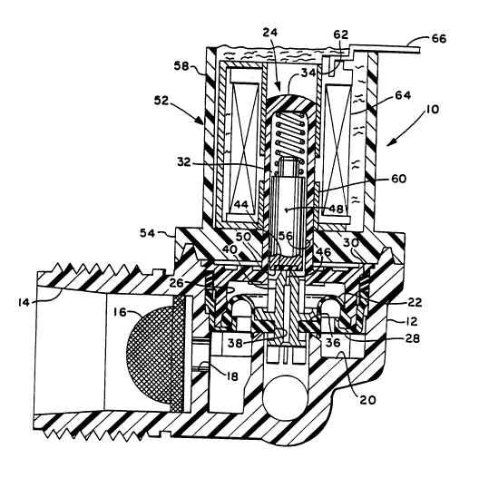
BRIEF DESCRIPTION OF THE DRAWINGS
FIGURE 1 is a cross-sectional view of a valve assembly
employing the present invention; and,
FIGURE 2 is an enlarged view of a portion of Figure 1.

90-CON-110 (AP) 0829K
Page 3
- 2040568

SUMMARY OF T~ INVENTION

The valve assembly of the present invention is
indicated generally at lO having a body 12 formed of
suitable plastic material with an inlet 14 formed therein
with a filter screen 16. The inlet 14 communicates
05 through passage 18 with a main valving chamber 20. The
valving chamber 20 is closed by a flexible diaphragm 22
having the periphery thereof sealed about the rim of a
bell-shaped armature guide member indicated generally at
24, with the diaphragm sealed about the rim enlarged
diameter portion 26 thereof. The rim of the diaphragm is
retained on the rim of the enlarged diameter portion 26 of
the armature guide by a suitable annular band 28 having a
generally U-shaped cross section. The band 28 and the
enlarged portion 26 of the armature are sealed in the
valving cavity 20 by a suitable sealing ring 30.
The upper portion of armature guide 24 comprises a
reduced diameter hollow tubular portion 32 having the
upper end 34 thereof closed.
The flexible diaphragm 22 has a thickened center
portion 36 which has a generally flat undersurface 37 and
a central aperture 38 formed therethrough. A rigid insert
40 is received through aperture 38 which insert has a
pilot valve seat 42 provided on the upper end thereof with
a central pilot passage 46 provided therethrough.
A movable valve member is slidably received in the
hollow interior of the upper portion 32 of the armature
guide 24 and comprises ferromagnetic armature 48 having an
elastomeric pad 50 provided in the lower end thereof which
contacts the pilot valve seat 44.
The armature guide 24 is retained in the body by an
annular cup member indicated generally at 52 which has a
thickened closed end portion having a radially outwardly
extending flange 54 which is sealed over the body and

90-CON-110 (AP) 0829K
Page 4 2040568
-

retained thereon by suitable weldment. The upper tubular
portion 32 of the armature guide extends through an
aperture 56 provided in the cup member.
The upper cylindrical wall portion 58 of the cup 52
05 has received therein tubular ferromagnetic pole pieces 60,
62, which pole pieces are separated by an axial air gap.
A suitable electrical solenoid coil 64 is received
thereover and is potted in the cup 52. Suitable
electrical terminals such as terminal strip 64 extend from
coil 64 outwardly of the cup for electrical connection
thereto.
Referring particularly to Figure 2, the valving cavity
20 has formed therein an annular main valve seat 68 which
surrounds and communicates with outlet passage 70 which is
open to the valve outlet 72.
The pilot passage 46 of insert 40 also communicates
with passage 70 through the diaphragm central portion 36.
The main valve valve seat 68 is contacted by the
undersurface 37 of the valving portion 96 of the diaphragm
when the valve is in the closed position as shown in the
drawings.
It will be understood that the main valve seat 37 is
moved upwardly away from seat 68 when the valve is in the
open position.
The main valve seat 68 is surrounded radially
outwardly thereof by a secondary preferably tapered
surface 74 extending downwardly therefrom.
An annular wiper portion 76 is formed integrally with
the undesurface 37 of the diaphragm and the wiper 76 has
the rim thereof sized and configured to contact the
tapered surface 74 prior to the closing of the main valve
member against seat 68 such that the wiper 76 seals
preferably slidably along surface 74 and is stretched
outwardly as the main valving surface 37 seats against

90-CON-110 (AP) 0829K
Page 5
2040568

main valve seat 68. The wiper 76 thus provides a
redundant sealing of the main valve. The region between
the wiper 76 and the main valve seat 68, denoted by
reference numeral 78, provides a suitable annular space to
05 trap foreign particles which may have passed through the
screen 16 and which might otherwise prevent the main valve
seat from being closed.
The wiper 76 thus enables an existing valve design to
be modified by changing only the taper of the conical
surface 74 and the addition of the wiper 76 to the
fle~ible diaphragm to provide for improved redundant
sealing of the main valve and provides protection against
lodgement of foreign particles which might prevent the
valve from fully closing.
Although the invention has hereinabove been described
with respect to the illustrated embodiments, it will be
understood that the invention is limited only by the
following claims:

Dessin représentatif
Une figure unique qui représente un dessin illustrant l'invention.
États administratifs

Pour une meilleure compréhension de l'état de la demande ou brevet qui figure sur cette page, la rubrique Mise en garde , et les descriptions de Brevet , États administratifs , Taxes périodiques et Historique des paiements devraient être consultées.

États administratifs

Titre Date
Date de délivrance prévu 1995-05-09
(22) Dépôt 1991-04-16
(41) Mise à la disponibilité du public 1991-10-26
Requête d'examen 1993-03-25
(45) Délivré 1995-05-09
Réputé périmé 1997-04-16

Historique d'abandonnement

Il n'y a pas d'historique d'abandonnement

Historique des paiements

Type de taxes Anniversaire Échéance Montant payé Date payée
Le dépôt d'une demande de brevet 0,00 $ 1991-04-16
Enregistrement de documents 0,00 $ 1991-10-22
Taxe de maintien en état - Demande - nouvelle loi 2 1993-04-16 100,00 $ 1993-02-11
Taxe de maintien en état - Demande - nouvelle loi 3 1994-04-18 100,00 $ 1994-03-23
Taxe de maintien en état - Demande - nouvelle loi 4 1995-04-17 100,00 $ 1995-03-21
Titulaires au dossier

Les titulaires actuels et antérieures au dossier sont affichés en ordre alphabétique.

Titulaires actuels au dossier
EATON CORPORATION
Titulaires antérieures au dossier
DONNER, RICHARD A.
Les propriétaires antérieurs qui ne figurent pas dans la liste des « Propriétaires au dossier » apparaîtront dans d'autres documents au dossier.
Documents

Pour visionner les fichiers sélectionnés, entrer le code reCAPTCHA :


Pour visualiser une image, cliquer sur un lien dans la colonne description du document. Pour télécharger l'image (les images), cliquer l'une ou plusieurs cases à cocher dans la première colonne et ensuite cliquer sur le bouton "Télécharger sélection en format PDF (archive Zip)" ou le bouton "Télécharger sélection (en un fichier PDF fusionné)".

Liste des documents de brevet publiés et non publiés sur la BDBC .

Si vous avez des difficultés à accéder au contenu, veuillez communiquer avec le Centre de services à la clientèle au 1-866-997-1936, ou envoyer un courriel au Centre de service à la clientèle de l'OPIC.


Description du
Document 
Date
(yyyy-mm-dd) 
Nombre de pages   Taille de l'image (Ko) 
Abrégé 1995-05-09 1 14
Dessins 1995-05-09 2 56
Page couverture 1995-05-09 1 16
Revendications 1995-05-09 2 84
Description 1995-05-09 6 237
Dessins représentatifs 1999-08-19 1 33
Correspondance de la poursuite 1993-03-25 1 22
Correspondance reliée au PCT 1995-02-27 1 29
Correspondance de la poursuite 1994-08-09 2 42
Lettre du bureau 1993-04-14 1 68
Demande d'examen 1994-04-22 1 58
Taxes 1995-03-21 1 74
Taxes 1994-03-23 1 62
Taxes 1993-02-11 1 64