Note: Descriptions are shown in the official language in which they were submitted.
20667~7
Control Device for Hydraulic Operatina Cylinders of a
Combined Lifting Platform and Closing Wall of a Vehicle
The invention relates to a control device for
hydraulic operating cylinders of a combined lifting platform
and closing wall of a vehicle, having a motor-driven
hydraulic fluid pump, which can be made to communicate with
a fluid supply and, via pump branch lines beginning at a
pump line, with a chamber of at least one lifting cylinder
and of at least one closing cylinder of the lifting platform
and closing wall, respectively, via associated control
valves; a pressure transformer and piston cylinder unit is
connected parallel to the pump branch lines.
In previously known control device of this type, the
problem has arisen in practice that if the load is not
positioned on the lifting platform and closing wall in
accordance with regulations, tilting moments arise that
i translate into increased tensile and compressive forces in
the lifting arms and closing cylinders of the lifting
platform and closing wall. For instance, the allowable
forces may be exceaded by up to a factor of 5, which can
damagè or destroy the lifting arms and/or closing cylinders.
The object of the invention is to create a device of
the type indicated at the outset above that averts the
dangers discussed above. The device according to the
invention has the characteristics that an electrical switch,
with which the pump motor drive can be shut down if a
predetermined pressure is exceeded, or an adjustable
:: :
. . .
2~6727
hydraulic valve, by way of which the pump branch lines can
be blocked off or the pump line can be made to communicate
with a return line to the fluid supply, and with which the
pump motor can optionally be shut down, is connected to the
chamber, communicating with the closing cylinder, of the
smaller end of the piston of the pressure transformer and
piston-cylinder unit.
As a result, in a structurally simple manner, the
pump motor is shut down and/or the hydraulic fluid feed line
is blocked off before an overload on the components of the
lifting platform and closing wall that form the lifting arms
and closing cylinders occurs.
Preferably, a counter mechanism for counting the
number of times the pressure is exceeded can be activated by
the electric pressure switch or by the adjustable hydraulic
valve.
The invention is described in further detail below in
terms of exemplary embodiments, referring to the drawings,
in which:
Fig. 1 shows a hydraulic circuit diagram of a control
device according to the invention; and
Fig. 2 is a circuit diagram of an alternative
embodiment.
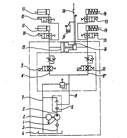
According to Fig. 1, a hydraulic fluid pump 1 is
driven by an electric motor 2 and communicates via a line 3
with a hydraulic fluid supply 4. The pump 1 also
communicates via a pump line 5, which includes a check valve
6, with a fluid return line 7 and with a line 8 that
branches into branch lines 8', 8". The left-hand branch 8'
in Fig. 1, via a controllable lifting valve 9 and two
.
,
20~6727
controllable lifting cylinder valves 10, feeds two lifting
cylinders 11 of the lifting platform and closing wall~ which
is not shown.
Analogously, the right-hand branch line 8" in Fig. 1,
via a controllable closing valve 12 and two controllable
closing cylinder valves 13, feeds two closing cylinders 14
of the lifting platform and closing wall. Between the valve
9 and 10 on one side and the valve 12 and 13 on the other, a
pressure transformer and piston-cylinder unit 15, the larger
piston end of which is oriented toward the lifting cylinder,
is connected to the branch lines 8', 8".
An adjustable electric pressure switch 16 is
connected in Fig. 1 to the smaller chamber of the pressure
transformer and piston-cylinder unit 15 and in turn
communicates with a counting mechanism 17 and an interrupter
switch 18 for the electric pump motor connection line. The
pressure switch 16 is for instance set to 220 bar, if the
left-hand side of the pressure transformer is set to 180
bar.
The counting mechanism 17 is sealed inside the
control system of the lifting platform and closing wall, and
each time there is an overload it switches onward by one
place, in order to record the number of times the load is
exceeded over a relatively long period of time.
According to the embodiment shown in Fig. 2, the
pressùre switch 17 of Fig. 1 is replaced by an adjustable
hydraulic shuttle valve or cutoff valve 19 connected to the
smaller chamber of the pressure transformer and piston-
cylinder unit 15; this valve is incorporated into the
branching point of the point branch lines 8', 8" and blocks
-3-
,
.. . . , , . . . . , -
..
- , .
2~667~7
them off if a predetermined pressure, for instance 220 bar,
is exceeded. Optionally, the electrical pump motor feed
line can also be interrupted via this hydraulic valve.
Instead of the hydraulic valve shown, a piston slide or the
like could also be provided. Via the hydraulic valve, a
counter mechanism can also be activated, analogously to the
counting mechanism 17.
The invention is not limited to the examples shown;
on the contrary, they can be modified in various ways within
the scope of the general concept of the invention. For
instance, particularly with the version shown in Fig. 2, a
hydraulic valve l9 may be provided, which in the event of an
overload puts the pump line 8 into communication with the
fluid return line 7, so that the pump runs empty.
':
~ '
:: :
-
. :. . . . .