Sélection de la langue

Search

Sommaire du brevet 2066727 

Énoncé de désistement de responsabilité concernant l'information provenant de tiers

Une partie des informations de ce site Web a été fournie par des sources externes. Le gouvernement du Canada n'assume aucune responsabilité concernant la précision, l'actualité ou la fiabilité des informations fournies par les sources externes. Les utilisateurs qui désirent employer cette information devraient consulter directement la source des informations. Le contenu fourni par les sources externes n'est pas assujetti aux exigences sur les langues officielles, la protection des renseignements personnels et l'accessibilité.

Disponibilité de l'Abrégé et des Revendications

L'apparition de différences dans le texte et l'image des Revendications et de l'Abrégé dépend du moment auquel le document est publié. Les textes des Revendications et de l'Abrégé sont affichés :

  • lorsque la demande peut être examinée par le public;
  • lorsque le brevet est émis (délivrance).
(12) Demande de brevet: (11) CA 2066727
(54) Titre français: DISPOSITIF DE COMMANDE DES VERINS HYDRAULIQUES DE PLATE-FORME DE LEVAGE/HAYON PLEINE HAUTEUR
(54) Titre anglais: CONTROL DEVICE FOR HYDRAULIC WORKING CYLINDERS OF A LOADING BOARD WALL OF A VEHICLE
Statut: Morte
Données bibliographiques
(51) Classification internationale des brevets (CIB):
  • B60P 1/16 (2006.01)
  • F15B 3/00 (2006.01)
(72) Inventeurs :
  • WEBER, GUNTER (Autriche)
(73) Titulaires :
  • WEBER, GUNTER (Autriche)
(71) Demandeurs :
  • WEBER, GUNTER (Autriche)
(74) Agent: FETHERSTONHAUGH & CO.
(74) Co-agent:
(45) Délivré:
(86) Date de dépôt PCT: 1990-09-10
(87) Mise à la disponibilité du public: 1991-03-14
Licence disponible: S.O.
(25) Langue des documents déposés: Anglais

Traité de coopération en matière de brevets (PCT): Oui
(86) Numéro de la demande PCT: PCT/AT1990/000090
(87) Numéro de publication internationale PCT: WO1991/004169
(85) Entrée nationale: 1992-03-12

(30) Données de priorité de la demande:
Numéro de la demande Pays / territoire Date
A 2139/89 Autriche 1989-09-13

Abrégés

Abrégé anglais


Control Device for Hydraulic Operating Cylinders of a
Combined Lifting Platform and Closing Wall of a Vehicle

Abstract:

A control device for hydraulic operating cylinders of
a combined lifting platform and closing wall of a vehicle,
having a hydraulic fluid pump (1), driven by a motor (2),
which pump can be made to communicate with a fluid supply
(4) and, via pump branch lines (8', 8") beginning at a pump
line (8), with a chamber of at least one lifting cylinder
(11) and of at least one closing cylinder (14) of the
lifting platform and closing wall, respectively, via
associated control valves (9, 10; 12, 13), wherein a
pressure transformer and piston cylinder unit (15) is
connected parallel to the pump branch lines (8', 8"), and
wherein an electrical switch (16), with which the pump motor
(2) can be shut down if a predetermined pressure is
exceeded, or an adjustable hydraulic valve, by way of which
the pump branch lines (8', 8") can be blocked off or the
pump line (8) can be made to communicate with a return line
(7) to the fluid supply (4), and with which the pump motor
(2) can optionally be shut down, is connected to the
chamber, communicating with the closing cylinder(s) (14), of
the smaller end of the piston of the pressure transformer
and piston-cylinder unit (15).
Fig. 1


-7-

Revendications

Note : Les revendications sont présentées dans la langue officielle dans laquelle elles ont été soumises.


CLAIMS:

1. A control device for hydraulic operating
cylinders of a combined lifting platform and closing wall of
a vehicle, having a hydraulic fluid pump (1) driven by a
motor (2), which pump can be made to communicate with a
fluid supply (4) and, via pump branch lines (8', 8")
beginning at a pump line (5, 8), with a chamber of at least
one lifting cylinder (11) and of at least one closing
cylinder (14) of the lifting platform and closing wall,
respectively, via associated control valves (10; 13),
wherein a pressure transformer and piston cylinder unit (15)
is connected parallel to the pump branch lines,
characterized in that an electrical pressure switch (16),
with which the pump motor drive can be shut down if a
predetermined pressure is exceeded, or an adjustable
hydraulic valve (19), by way of which the pump branch lines
(8', 8") can be blocked off or the pump line (8) can be made
to communicate with a return line (7) to the fluid supply
(4), and with which the pump motor can optionally be shut
down, is connected to the chamber, communicating with the
closing cylinder (14), of the smaller end of the piston of
the pressure transformer and piston-cylinder unit (15).

2. A control device of claim 1, characterized in
that the adjustable hydraulic valve (19) for blocking off
the pump branch lines (8', 8") is formed by a shuttle valve.


-1-


3. A control device of claim 1, characterized in
that a counting mechanism (17) for the number of times the
pressure is exceeded is activatable by the electric pressure
switch (16) or by the adjustable hydraulic valve (19).


-2-

Description

Note : Les descriptions sont présentées dans la langue officielle dans laquelle elles ont été soumises.


20667~7


Control Device for Hydraulic Operatina Cylinders of a
Combined Lifting Platform and Closing Wall of a Vehicle

The invention relates to a control device for
hydraulic operating cylinders of a combined lifting platform
and closing wall of a vehicle, having a motor-driven
hydraulic fluid pump, which can be made to communicate with
a fluid supply and, via pump branch lines beginning at a
pump line, with a chamber of at least one lifting cylinder
and of at least one closing cylinder of the lifting platform
and closing wall, respectively, via associated control
valves; a pressure transformer and piston cylinder unit is
connected parallel to the pump branch lines.
In previously known control device of this type, the
problem has arisen in practice that if the load is not
positioned on the lifting platform and closing wall in
accordance with regulations, tilting moments arise that
i translate into increased tensile and compressive forces in
the lifting arms and closing cylinders of the lifting
platform and closing wall. For instance, the allowable
forces may be exceaded by up to a factor of 5, which can
damagè or destroy the lifting arms and/or closing cylinders.
The object of the invention is to create a device of
the type indicated at the outset above that averts the
dangers discussed above. The device according to the
invention has the characteristics that an electrical switch,
with which the pump motor drive can be shut down if a
predetermined pressure is exceeded, or an adjustable
:: :


. . .

2~6727


hydraulic valve, by way of which the pump branch lines can
be blocked off or the pump line can be made to communicate
with a return line to the fluid supply, and with which the
pump motor can optionally be shut down, is connected to the
chamber, communicating with the closing cylinder, of the
smaller end of the piston of the pressure transformer and
piston-cylinder unit.
As a result, in a structurally simple manner, the
pump motor is shut down and/or the hydraulic fluid feed line
is blocked off before an overload on the components of the
lifting platform and closing wall that form the lifting arms
and closing cylinders occurs.
Preferably, a counter mechanism for counting the
number of times the pressure is exceeded can be activated by
the electric pressure switch or by the adjustable hydraulic
valve.
The invention is described in further detail below in
terms of exemplary embodiments, referring to the drawings,
in which:
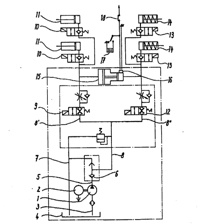
Fig. 1 shows a hydraulic circuit diagram of a control
device according to the invention; and
Fig. 2 is a circuit diagram of an alternative
embodiment.
According to Fig. 1, a hydraulic fluid pump 1 is
driven by an electric motor 2 and communicates via a line 3
with a hydraulic fluid supply 4. The pump 1 also
communicates via a pump line 5, which includes a check valve
6, with a fluid return line 7 and with a line 8 that
branches into branch lines 8', 8". The left-hand branch 8'
in Fig. 1, via a controllable lifting valve 9 and two

.


,

20~6727


controllable lifting cylinder valves 10, feeds two lifting
cylinders 11 of the lifting platform and closing wall~ which
is not shown.
Analogously, the right-hand branch line 8" in Fig. 1,
via a controllable closing valve 12 and two controllable
closing cylinder valves 13, feeds two closing cylinders 14
of the lifting platform and closing wall. Between the valve
9 and 10 on one side and the valve 12 and 13 on the other, a
pressure transformer and piston-cylinder unit 15, the larger
piston end of which is oriented toward the lifting cylinder,
is connected to the branch lines 8', 8".
An adjustable electric pressure switch 16 is
connected in Fig. 1 to the smaller chamber of the pressure
transformer and piston-cylinder unit 15 and in turn
communicates with a counting mechanism 17 and an interrupter
switch 18 for the electric pump motor connection line. The
pressure switch 16 is for instance set to 220 bar, if the
left-hand side of the pressure transformer is set to 180
bar.
The counting mechanism 17 is sealed inside the
control system of the lifting platform and closing wall, and
each time there is an overload it switches onward by one
place, in order to record the number of times the load is
exceeded over a relatively long period of time.
According to the embodiment shown in Fig. 2, the
pressùre switch 17 of Fig. 1 is replaced by an adjustable
hydraulic shuttle valve or cutoff valve 19 connected to the
smaller chamber of the pressure transformer and piston-
cylinder unit 15; this valve is incorporated into the
branching point of the point branch lines 8', 8" and blocks

-3-


,

.. . . , , . . . . , -


..
- , .

2~667~7


them off if a predetermined pressure, for instance 220 bar,
is exceeded. Optionally, the electrical pump motor feed
line can also be interrupted via this hydraulic valve.
Instead of the hydraulic valve shown, a piston slide or the
like could also be provided. Via the hydraulic valve, a
counter mechanism can also be activated, analogously to the
counting mechanism 17.
The invention is not limited to the examples shown;
on the contrary, they can be modified in various ways within
the scope of the general concept of the invention. For
instance, particularly with the version shown in Fig. 2, a
hydraulic valve l9 may be provided, which in the event of an
overload puts the pump line 8 into communication with the
fluid return line 7, so that the pump runs empty.
':


~ '
:: :
-

. :. . . . .
Dessin représentatif
Une figure unique qui représente un dessin illustrant l'invention.
États administratifs

Pour une meilleure compréhension de l'état de la demande ou brevet qui figure sur cette page, la rubrique Mise en garde , et les descriptions de Brevet , États administratifs , Taxes périodiques et Historique des paiements devraient être consultées.

États administratifs

Titre Date
Date de délivrance prévu Non disponible
(86) Date de dépôt PCT 1990-09-10
(87) Date de publication PCT 1991-03-14
(85) Entrée nationale 1992-03-12
Demande morte 1998-09-10

Historique d'abandonnement

Date d'abandonnement Raison Reinstatement Date
1997-09-10 Absence de requête d'examen
1997-09-10 Taxe périodique sur la demande impayée

Historique des paiements

Type de taxes Anniversaire Échéance Montant payé Date payée
Le dépôt d'une demande de brevet 0,00 $ 1992-03-12
Taxe de maintien en état - Demande - nouvelle loi 2 1992-09-10 50,00 $ 1992-03-12
Rétablissement: taxe de maintien en état non-payées pour la demande 200,00 $ 1993-12-10
Taxe de maintien en état - Demande - nouvelle loi 3 1993-09-10 50,00 $ 1993-12-10
Taxe de maintien en état - Demande - nouvelle loi 4 1994-09-12 50,00 $ 1994-08-24
Taxe de maintien en état - Demande - nouvelle loi 5 1995-09-11 75,00 $ 1995-08-30
Rétablissement: taxe de maintien en état non-payées pour la demande 200,00 $ 1997-01-17
Taxe de maintien en état - Demande - nouvelle loi 6 1996-09-10 75,00 $ 1997-01-17
Titulaires au dossier

Les titulaires actuels et antérieures au dossier sont affichés en ordre alphabétique.

Titulaires actuels au dossier
WEBER, GUNTER
Titulaires antérieures au dossier
S.O.
Les propriétaires antérieurs qui ne figurent pas dans la liste des « Propriétaires au dossier » apparaîtront dans d'autres documents au dossier.
Documents

Pour visionner les fichiers sélectionnés, entrer le code reCAPTCHA :


Pour visualiser une image, cliquer sur un lien dans la colonne description du document. Pour télécharger l'image (les images), cliquer l'une ou plusieurs cases à cocher dans la première colonne et ensuite cliquer sur le bouton "Télécharger sélection en format PDF (archive Zip)" ou le bouton "Télécharger sélection (en un fichier PDF fusionné)".

Liste des documents de brevet publiés et non publiés sur la BDBC .

Si vous avez des difficultés à accéder au contenu, veuillez communiquer avec le Centre de services à la clientèle au 1-866-997-1936, ou envoyer un courriel au Centre de service à la clientèle de l'OPIC.


Description du
Document 
Date
(yyyy-mm-dd) 
Nombre de pages   Taille de l'image (Ko) 
Rapport d'examen préliminaire international 1992-03-12 29 827
Page couverture 1991-03-14 1 23
Abrégé 1991-03-14 1 40
Revendications 1991-03-14 2 51
Dessins 1991-03-14 2 47
Dessins représentatifs 1999-09-30 1 15
Description 1991-03-14 4 145
Taxes 1997-01-17 2 59
Taxes 1995-08-30 1 37
Taxes 1994-08-24 1 35
Taxes 1993-12-10 2 43
Taxes 1992-03-12 2 70