Language selection

Search

Patent 2070564 Summary

Third-party information liability

Some of the information on this Web page has been provided by external sources. The Government of Canada is not responsible for the accuracy, reliability or currency of the information supplied by external sources. Users wishing to rely upon this information should consult directly with the source of the information. Content provided by external sources is not subject to official languages, privacy and accessibility requirements.

Claims and Abstract availability

Any discrepancies in the text and image of the Claims and Abstract are due to differing posting times. Text of the Claims and Abstract are posted:

  • At the time the application is open to public inspection;
  • At the time of issue of the patent (grant).
(12) Patent: (11) CA 2070564
(54) English Title: SNOW PLOW SUPPORT DEVICE
(54) French Title: DISPOSITIF DE SUPPORT D'UN CHASSE-NEIGE
Status: Deemed expired
Bibliographic Data
(51) International Patent Classification (IPC):
  • E01H 5/04 (2006.01)
  • E01H 5/06 (2006.01)
(72) Inventors :
  • ATKINSON, MITCH (United States of America)
(73) Owners :
  • ATKINSON, MITCH (United States of America)
(71) Applicants :
(74) Agent: MACRAE & CO.
(74) Associate agent:
(45) Issued: 1995-01-03
(22) Filed Date: 1992-06-05
(41) Open to Public Inspection: 1993-01-11
Examination requested: 1993-07-13
Availability of licence: N/A
(25) Language of filing: English

Patent Cooperation Treaty (PCT): No

(30) Application Priority Data:
Application No. Country/Territory Date
727,874 United States of America 1991-07-10

Abstracts

English Abstract


ABSTRACT OF THE DISCLOSURE


A swivel design for a wear shoe is described which provides support
to apparatus cantilevered from a vehicle. This effectively reduces wear to
the contacting surface by distributing the wear more evenly. To accomplish
this objective the wear shoe is mounted to the supported structure by a
swivel joint which allows full freedom of movement. During use the wear
shoe tilts and rotates on the swivel to maintain the wear surface of the shoe
in facing relation to the road surface.


Claims

Note: Claims are shown in the official language in which they were submitted.


CLAIMS


1. A supporting device for use with snow plows or other vehicle mounted
apparatus being moved in controlled proximity to a road surface, the
supporting device comprising:
a surface contacting member;
mounting means for securing said supporting device to the vehicle
mounted apparatus; and
means for attaching said surface contacting member to said mounting
means and for allowing said surface contacting member to adjust
position in conformity with the traversed road surface.


2. The supporting device of Claim 1 wherein said surface contacting
member is spherically shaped.


3. The supporting device of Claim 1 wherein said surface contacting
member is comprised of an upper mounting portion and a lower wear
surface portion, wherein the sides of said surface contacting member
converge toward said lower wear surface portion.


4. The supporting device of Claim 1 wherein said means for attaching
said surface contacting member to said mounting means comprises a swivel
joint.


5. The supporting device of Claim 4 wherein said swivel joint comprises
a ball and socket joint.


6. The supporting device of Claim S wherein said ball is affixed to said
mounting means and said socket is formed in said surface contacting
member, and said ball is held into said socket by removable cover plates.


7. The supporting device of Claim 3 wherein said swivel joint comprises
a ball and socket joint.


8. The supporting device of Claim 7 wherein said ball is affixed to said
mounting means and said socket is formed in said surface contacting
member, and said ball is held into said socket by removable cover plates.


Description

Note: Descriptions are shown in the official language in which they were submitted.


2070~6~


SNOW PLOW SUPPORT DEVICE


3 BACKGROUND OF THE lNVENl~ION
4 Field of the Invention
The present invention relates generally to devices used to assist in the
6 support of structures, such as snow plows or the like, which are mounted to
7 vehicles. More particularly this invention relates to devices known as
8 support runners and drag shoes which are affixed $o the underside of such
9 structures.

11 Description of the Prior Art
12 Snow plows and similar apparatus are typically cantilevered from the
13 chassis of a vehicle. Runners, wear shoes and wheels have been used to
14 pro~1ide support for the overhanging extremity of the structure and to
maintain the apparatus at a preset elevation over the road surface. While
16 prior wear resistant support devices have achieved limited success, excessive
17 wear and premature failure have remained a dangerous problem. Use of
18 wheels has proven to be unstable and similarly subject to excessive wear and
19 premature failure.


2070~6~


SUMMARY OF THE INVENTION


3 It is accordingly the principal object of the present invention to
4 provide a safer wear shoe for snow plows and the like which effect;vely
reduces wear to the contacting surface and distributes wear more evenly.
6 This is accomplished in the preferred embodiment by providing a wear shoe
7 which presents a wear surface to the road and provides continuous
8 automatic alignment to present the wear surface tangentially against the road
9 surface. In the preferred embodiment this wear shoe presents a generally
spherically shaped surface, having sides chamfered inwardly toward the
11 contacting surface. Most importantly, this shoe is mounted to the supported12 structure by a swivel joint which allows full freedom of movement. During
13 use the wear shoe is allowed to tilt and rotate on the swivel to minimize
14 wear on the contacting surface.


207056~


BRIEF DESCRIPTION OF THE DRAWINGS


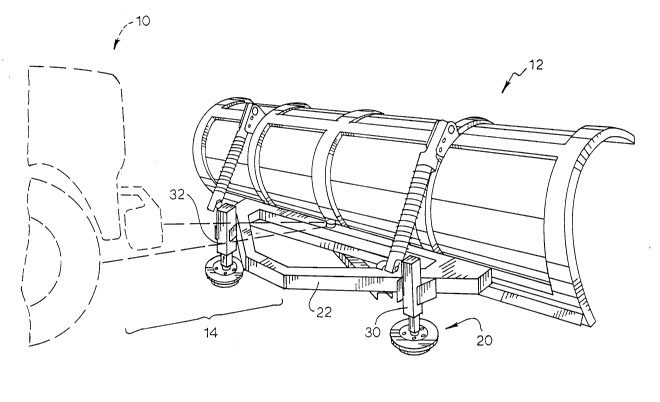
3 Figure 1 is a perspective view of a snow plow employing the wear
4 shoes of the present invention.
Figure 2 is a perspective view of a wear shoe of Figure 1.
6 Figure 3 is a cross sectional view of the wear shoe depicted in Figure
7 2, showing (in phantom) the tilting and swiveling motion of the shoe.
8 While the invention will be describ~d in connection vith a preferred
9 embodiment, it will be understood that it is not the intent to limit the
invention to that embodiment. On the contrary, it is the intent to cover all
11 alternatives, modifications, and equivalents as may be included within the
1~ spirit and scope of the invention as defined by the appended claims.
13

2070~6~


DESCRIPTION OF THE PREFERRED EMBODIMENT


3 Turning first to Figure 1 there is shown a vehicle 10 having a plow 12
4 cantilevered to the vehicle 10 via supports 14 shown in phantom. Further
supporting the plow, in accordance with the present invention, are wear
6 shoes 20 shown affixed to the plow support bracket 22. During use of the
7 plow, the wear shoes ride on the road surface to ~hereby position and
8 support the plow at a pre-selected elevation above the road surface. This
9 elevational positioning of the plow is accomplished by adjusting means at the
mounting posts 30 and 32; and such adjustment may take the form of a
11 screw thread, a hand crank, or any other device or method commonly known
12 in the art.
13 In the preferred embodiment, the wear shoe 20 presents a generally
14 spherical shape (Figure 2) to the road surface; and in the preferred
embodiment shown in Figure 3, it e~ibits chamfered sides 52 and 54 and
16 a generally flattened bottom face 56. Securing the shoe to the mounting
17 post is a swivel joint 60 comprising a ball 62 mounted into a socket formed18 in the shoe. And the ball is held into the socket by removable plates 64 and
19 66 which are bolted to the shoe.

2070~64


During use, the contacting surface 56 of the wear shoe rides against
2 and faces the road surface; and due to the swivel joint, the shoe is allowed
3 to "tilt" in all directions to constantly maintain the wear surface of the shoe
4 in facing relation against the road surface. Concentration of wear on aS limited portion of the shoe is avoided and the life of the shoe is thereby
6 extended. The chamfered sides of the shoe which produce the spherical
7 nature of its shape facilitate use on rough roads and allow the shoe to "ride
8 over" small bumps.
9 From the foregoing description, it will be apparent that modifications
can be made to the apparatus and method ~or using same without departing
11 from the teachings of the present invention. Accordingly, the scope of the
12 invention is only to be limited as necessitated by the accompanying claims.
13
Representative Drawing
A single figure which represents the drawing illustrating the invention.
Administrative Status

For a clearer understanding of the status of the application/patent presented on this page, the site Disclaimer , as well as the definitions for Patent , Administrative Status , Maintenance Fee  and Payment History  should be consulted.

Administrative Status

Title Date
Forecasted Issue Date 1995-01-03
(22) Filed 1992-06-05
(41) Open to Public Inspection 1993-01-11
Examination Requested 1993-07-13
(45) Issued 1995-01-03
Deemed Expired 1995-12-05

Abandonment History

There is no abandonment history.

Payment History

Fee Type Anniversary Year Due Date Amount Paid Paid Date
Application Fee $0.00 1992-06-05
Maintenance Fee - Application - New Act 2 1994-06-06 $50.00 1994-05-10
Owners on Record

Note: Records showing the ownership history in alphabetical order.

Current Owners on Record
ATKINSON, MITCH
Past Owners on Record
None
Past Owners that do not appear in the "Owners on Record" listing will appear in other documentation within the application.
Documents

To view selected files, please enter reCAPTCHA code :


To view images, click a link in the Document Description column. To download the documents, select one or more checkboxes in the first column and then click the "Download Selected in PDF format (Zip Archive)" or the "Download Selected as Single PDF" button.

List of published and non-published patent-specific documents on the CPD .

If you have any difficulty accessing content, you can call the Client Service Centre at 1-866-997-1936 or send them an e-mail at CIPO Client Service Centre.


Document
Description 
Date
(yyyy-mm-dd) 
Number of pages   Size of Image (KB) 
Cover Page 1995-01-03 1 15
Abstract 1995-01-03 1 15
Description 1995-01-03 5 141
Claims 1995-01-03 1 30
Drawings 1995-01-03 2 40
Representative Drawing 1998-10-30 1 24
Examiner Requisition 1994-04-19 2 81
Prosecution Correspondence 1994-05-17 2 45
Prosecution Correspondence 1993-08-26 1 26
PCT Correspondence 1994-10-05 2 43
Office Letter 1993-08-09 1 33
Prosecution Correspondence 1993-07-13 1 19
Fees 1994-05-10 1 56