Sélection de la langue

Search

Sommaire du brevet 2070564 

Énoncé de désistement de responsabilité concernant l'information provenant de tiers

Une partie des informations de ce site Web a été fournie par des sources externes. Le gouvernement du Canada n'assume aucune responsabilité concernant la précision, l'actualité ou la fiabilité des informations fournies par les sources externes. Les utilisateurs qui désirent employer cette information devraient consulter directement la source des informations. Le contenu fourni par les sources externes n'est pas assujetti aux exigences sur les langues officielles, la protection des renseignements personnels et l'accessibilité.

Disponibilité de l'Abrégé et des Revendications

L'apparition de différences dans le texte et l'image des Revendications et de l'Abrégé dépend du moment auquel le document est publié. Les textes des Revendications et de l'Abrégé sont affichés :

  • lorsque la demande peut être examinée par le public;
  • lorsque le brevet est émis (délivrance).
(12) Brevet: (11) CA 2070564
(54) Titre français: DISPOSITIF DE SUPPORT D'UN CHASSE-NEIGE
(54) Titre anglais: SNOW PLOW SUPPORT DEVICE
Statut: Réputé périmé
Données bibliographiques
(51) Classification internationale des brevets (CIB):
  • E01H 5/04 (2006.01)
  • E01H 5/06 (2006.01)
(72) Inventeurs :
  • ATKINSON, MITCH (Etats-Unis d'Amérique)
(73) Titulaires :
  • ATKINSON, MITCH (Etats-Unis d'Amérique)
(71) Demandeurs :
(74) Agent: MACRAE & CO.
(74) Co-agent:
(45) Délivré: 1995-01-03
(22) Date de dépôt: 1992-06-05
(41) Mise à la disponibilité du public: 1993-01-11
Requête d'examen: 1993-07-13
Licence disponible: S.O.
(25) Langue des documents déposés: Anglais

Traité de coopération en matière de brevets (PCT): Non

(30) Données de priorité de la demande:
Numéro de la demande Pays / territoire Date
727,874 Etats-Unis d'Amérique 1991-07-10

Abrégés

Abrégé anglais


ABSTRACT OF THE DISCLOSURE


A swivel design for a wear shoe is described which provides support
to apparatus cantilevered from a vehicle. This effectively reduces wear to
the contacting surface by distributing the wear more evenly. To accomplish
this objective the wear shoe is mounted to the supported structure by a
swivel joint which allows full freedom of movement. During use the wear
shoe tilts and rotates on the swivel to maintain the wear surface of the shoe
in facing relation to the road surface.

Revendications

Note : Les revendications sont présentées dans la langue officielle dans laquelle elles ont été soumises.


CLAIMS


1. A supporting device for use with snow plows or other vehicle mounted
apparatus being moved in controlled proximity to a road surface, the
supporting device comprising:
a surface contacting member;
mounting means for securing said supporting device to the vehicle
mounted apparatus; and
means for attaching said surface contacting member to said mounting
means and for allowing said surface contacting member to adjust
position in conformity with the traversed road surface.


2. The supporting device of Claim 1 wherein said surface contacting
member is spherically shaped.


3. The supporting device of Claim 1 wherein said surface contacting
member is comprised of an upper mounting portion and a lower wear
surface portion, wherein the sides of said surface contacting member
converge toward said lower wear surface portion.


4. The supporting device of Claim 1 wherein said means for attaching
said surface contacting member to said mounting means comprises a swivel
joint.


5. The supporting device of Claim 4 wherein said swivel joint comprises
a ball and socket joint.


6. The supporting device of Claim S wherein said ball is affixed to said
mounting means and said socket is formed in said surface contacting
member, and said ball is held into said socket by removable cover plates.


7. The supporting device of Claim 3 wherein said swivel joint comprises
a ball and socket joint.


8. The supporting device of Claim 7 wherein said ball is affixed to said
mounting means and said socket is formed in said surface contacting
member, and said ball is held into said socket by removable cover plates.


Description

Note : Les descriptions sont présentées dans la langue officielle dans laquelle elles ont été soumises.


2070~6~


SNOW PLOW SUPPORT DEVICE


3 BACKGROUND OF THE lNVENl~ION
4 Field of the Invention
The present invention relates generally to devices used to assist in the
6 support of structures, such as snow plows or the like, which are mounted to
7 vehicles. More particularly this invention relates to devices known as
8 support runners and drag shoes which are affixed $o the underside of such
9 structures.

11 Description of the Prior Art
12 Snow plows and similar apparatus are typically cantilevered from the
13 chassis of a vehicle. Runners, wear shoes and wheels have been used to
14 pro~1ide support for the overhanging extremity of the structure and to
maintain the apparatus at a preset elevation over the road surface. While
16 prior wear resistant support devices have achieved limited success, excessive
17 wear and premature failure have remained a dangerous problem. Use of
18 wheels has proven to be unstable and similarly subject to excessive wear and
19 premature failure.


2070~6~


SUMMARY OF THE INVENTION


3 It is accordingly the principal object of the present invention to
4 provide a safer wear shoe for snow plows and the like which effect;vely
reduces wear to the contacting surface and distributes wear more evenly.
6 This is accomplished in the preferred embodiment by providing a wear shoe
7 which presents a wear surface to the road and provides continuous
8 automatic alignment to present the wear surface tangentially against the road
9 surface. In the preferred embodiment this wear shoe presents a generally
spherically shaped surface, having sides chamfered inwardly toward the
11 contacting surface. Most importantly, this shoe is mounted to the supported12 structure by a swivel joint which allows full freedom of movement. During
13 use the wear shoe is allowed to tilt and rotate on the swivel to minimize
14 wear on the contacting surface.


207056~


BRIEF DESCRIPTION OF THE DRAWINGS


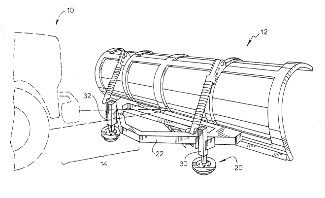
3 Figure 1 is a perspective view of a snow plow employing the wear
4 shoes of the present invention.
Figure 2 is a perspective view of a wear shoe of Figure 1.
6 Figure 3 is a cross sectional view of the wear shoe depicted in Figure
7 2, showing (in phantom) the tilting and swiveling motion of the shoe.
8 While the invention will be describ~d in connection vith a preferred
9 embodiment, it will be understood that it is not the intent to limit the
invention to that embodiment. On the contrary, it is the intent to cover all
11 alternatives, modifications, and equivalents as may be included within the
1~ spirit and scope of the invention as defined by the appended claims.
13

2070~6~


DESCRIPTION OF THE PREFERRED EMBODIMENT


3 Turning first to Figure 1 there is shown a vehicle 10 having a plow 12
4 cantilevered to the vehicle 10 via supports 14 shown in phantom. Further
supporting the plow, in accordance with the present invention, are wear
6 shoes 20 shown affixed to the plow support bracket 22. During use of the
7 plow, the wear shoes ride on the road surface to ~hereby position and
8 support the plow at a pre-selected elevation above the road surface. This
9 elevational positioning of the plow is accomplished by adjusting means at the
mounting posts 30 and 32; and such adjustment may take the form of a
11 screw thread, a hand crank, or any other device or method commonly known
12 in the art.
13 In the preferred embodiment, the wear shoe 20 presents a generally
14 spherical shape (Figure 2) to the road surface; and in the preferred
embodiment shown in Figure 3, it e~ibits chamfered sides 52 and 54 and
16 a generally flattened bottom face 56. Securing the shoe to the mounting
17 post is a swivel joint 60 comprising a ball 62 mounted into a socket formed18 in the shoe. And the ball is held into the socket by removable plates 64 and
19 66 which are bolted to the shoe.

2070~64


During use, the contacting surface 56 of the wear shoe rides against
2 and faces the road surface; and due to the swivel joint, the shoe is allowed
3 to "tilt" in all directions to constantly maintain the wear surface of the shoe
4 in facing relation against the road surface. Concentration of wear on aS limited portion of the shoe is avoided and the life of the shoe is thereby
6 extended. The chamfered sides of the shoe which produce the spherical
7 nature of its shape facilitate use on rough roads and allow the shoe to "ride
8 over" small bumps.
9 From the foregoing description, it will be apparent that modifications
can be made to the apparatus and method ~or using same without departing
11 from the teachings of the present invention. Accordingly, the scope of the
12 invention is only to be limited as necessitated by the accompanying claims.
13
Dessin représentatif
Une figure unique qui représente un dessin illustrant l'invention.
États administratifs

Pour une meilleure compréhension de l'état de la demande ou brevet qui figure sur cette page, la rubrique Mise en garde , et les descriptions de Brevet , États administratifs , Taxes périodiques et Historique des paiements devraient être consultées.

États administratifs

Titre Date
Date de délivrance prévu 1995-01-03
(22) Dépôt 1992-06-05
(41) Mise à la disponibilité du public 1993-01-11
Requête d'examen 1993-07-13
(45) Délivré 1995-01-03
Réputé périmé 1995-12-05

Historique d'abandonnement

Il n'y a pas d'historique d'abandonnement

Historique des paiements

Type de taxes Anniversaire Échéance Montant payé Date payée
Le dépôt d'une demande de brevet 0,00 $ 1992-06-05
Taxe de maintien en état - Demande - nouvelle loi 2 1994-06-06 50,00 $ 1994-05-10
Titulaires au dossier

Les titulaires actuels et antérieures au dossier sont affichés en ordre alphabétique.

Titulaires actuels au dossier
ATKINSON, MITCH
Titulaires antérieures au dossier
S.O.
Les propriétaires antérieurs qui ne figurent pas dans la liste des « Propriétaires au dossier » apparaîtront dans d'autres documents au dossier.
Documents

Pour visionner les fichiers sélectionnés, entrer le code reCAPTCHA :


Pour visualiser une image, cliquer sur un lien dans la colonne description du document. Pour télécharger l'image (les images), cliquer l'une ou plusieurs cases à cocher dans la première colonne et ensuite cliquer sur le bouton "Télécharger sélection en format PDF (archive Zip)" ou le bouton "Télécharger sélection (en un fichier PDF fusionné)".

Liste des documents de brevet publiés et non publiés sur la BDBC .

Si vous avez des difficultés à accéder au contenu, veuillez communiquer avec le Centre de services à la clientèle au 1-866-997-1936, ou envoyer un courriel au Centre de service à la clientèle de l'OPIC.


Description du
Document 
Date
(yyyy-mm-dd) 
Nombre de pages   Taille de l'image (Ko) 
Page couverture 1995-01-03 1 15
Abrégé 1995-01-03 1 15
Description 1995-01-03 5 141
Revendications 1995-01-03 1 30
Dessins 1995-01-03 2 40
Dessins représentatifs 1998-10-30 1 24
Demande d'examen 1994-04-19 2 81
Correspondance de la poursuite 1994-05-17 2 45
Correspondance de la poursuite 1993-08-26 1 26
Correspondance reliée au PCT 1994-10-05 2 43
Lettre du bureau 1993-08-09 1 33
Correspondance de la poursuite 1993-07-13 1 19
Taxes 1994-05-10 1 56