Language selection

Search

Patent 2082254 Summary

Third-party information liability

Some of the information on this Web page has been provided by external sources. The Government of Canada is not responsible for the accuracy, reliability or currency of the information supplied by external sources. Users wishing to rely upon this information should consult directly with the source of the information. Content provided by external sources is not subject to official languages, privacy and accessibility requirements.

Claims and Abstract availability

Any discrepancies in the text and image of the Claims and Abstract are due to differing posting times. Text of the Claims and Abstract are posted:

  • At the time the application is open to public inspection;
  • At the time of issue of the patent (grant).
(12) Patent Application: (11) CA 2082254
(54) English Title: PIVOTABLE JOINT
(54) French Title: JOINT PIVOTANT
Status: Deemed Abandoned and Beyond the Period of Reinstatement - Pending Response to Notice of Disregarded Communication
Bibliographic Data
(51) International Patent Classification (IPC):
  • F02D 09/10 (2006.01)
  • E05D 07/10 (2006.01)
  • F02D 09/02 (2006.01)
  • F16K 27/02 (2006.01)
(72) Inventors :
  • MUELLER, MANFRED (Germany)
  • WINTER, MANFRED (Germany)
(73) Owners :
  • FILTERWERK MANN & HUMEL GMBH
(71) Applicants :
  • FILTERWERK MANN & HUMEL GMBH (Germany)
(74) Agent: BORDEN LADNER GERVAIS LLP
(74) Associate agent:
(45) Issued:
(22) Filed Date: 1992-11-05
(41) Open to Public Inspection: 1993-05-06
Availability of licence: N/A
Dedicated to the Public: N/A
(25) Language of filing: English

Patent Cooperation Treaty (PCT): No

(30) Application Priority Data:
Application No. Country/Territory Date
G 91 13 727.6 (Germany) 1991-11-05

Abstracts

English Abstract


Abstract of the Disclosure
A pivotable joint including a first part provided with
pivot bores and a second part with resiliently mounted pivot
pins received in said pivot bores such that the second part
is pivotably mounted in a desired assembled position. The
first part has a closed tubular cross section and may be a
section of the intake manifold of an internal combustion
engine. The resiliently mounted pivot pins are
symmetrically mounted on opposite sides of the second part,
which may be a throttle valve. The pivot pins are
elastically displaceable axially during assembly of the
first and second parts such that they snap resiliently into
the pivot bores of the first part when the second part
reaches the desired assembled position.


Claims

Note: Claims are shown in the official language in which they were submitted.

THE EMBODIMENTS OF THE INVENTION IN WHICH AN EXCLUSIVE
PROPERTY OR PRIVILEGE IS CLAIMED ARE DEFINED AS FOLLOWS:
1. A pivotable joint comprising a first part provided
with pivot bores and a second part with resiliently mounted
pivot pins received in said pivot bores such that said
second part is pivotably mounted in a desired assembled
position relative to said first part, wherein said first
part has a closed tubular cross section, and wherein said
pivot pins of said second part are elastically displaceable
during assembly of said first and second parts and snap
resiliently into the pivot bores of said first part when
said second part reaches said desired assembled position.
2. A pivotable joint according to claim 1, wherein
said first part comprises a section of an intake manifold of
an internal combustion engine, and said second part is a
throttle valve disposed in said intake manifold.
3. A pivotable joint according to claim 1, wherein
stop means are provided on said second part for limiting the
resilient displacement of said pivot pins.
4. A pivotable joint according to claim 1, wherein
assembly grooves are provided on said first part for guiding
said resiliently mounted pivot pins of said second part to
said pivot bores of said first part during assembly of said
first and second parts.
5. A pivotable joint according to claim 1, further
comprising a mounting member formed on said second part for
connecting a control linkage for controlling pivoting of
said second part relative to said first part.
6. A pivotable joint according to claim 1, wherein
said elastic pivots are attached to opposite sides of said
second part.
- 4 -

7. A pivotable joint according to claim 6, wherein
said elastic pivots are symmetrically attached to opposite
sides of said second part.
8. A pivotable joint according to claim 1, wherein
said elastic pivots of said second part are deformable only
in the axial direction.
- 5 -

Description

Note: Descriptions are shown in the official language in which they were submitted.


21D~22~
PIVOTABLE JOINT
Background of the Invention
This invention relates to a pivotable joint in which a
first part is provided with pivot bores and a second part
with elastic mounting pins or pivot pins.
5Pivotable joints of this general type are known, e.g.,
in boxes for music cassettes. However, if it is desired to
use such pivotable joints, for example, in intake manifolds
with throttle valves, it is disadvantageous that the passage
cross section would have to be made elastic. This would
certainly be difficult and expensive. A housing could also
be provided which could be divided and then reassembled in
order to mount the throttle valve. This is, however, costly
to manufacture, and it would make the pivotable joint
expensive. Another possibility would be to mount the
throttle valve on a continuous shaft extended through pivot
bores. This, however, would be difficult to assemble and
would make it necessary afterward to seal up the intake
manifold.
Summary o~ the Invention
It is therefore the object o~ the invention to improve
a pivotable joint of the kind described above by providing
a pivotable joint which is simple, inexpensive and easy-to-
assemble and disassemble.
25These and other objects o~ the invention are achieved
by providing a pivotable joint comprising a first part with
pivot bores and a second part with pivot pins inserted in
-- 1 --

2~822~
the pivot bores of the first part, in which the first part
with the pivot bores has an unbroken tubular cross section,
the second part has resiliently mounted pivot pins which
during assembly deform or shift from their original
positions, and when the second part reaches the desired
assembled position relative to the first part, the elastic
pivot pins snap resiliently into the pivot bores of the
first part.
~n a particularly preferred embodiment of the
lo invention, the first part comprises a section of an intake
manifold of an internal combustion engine and the second
part is a throttle valve disposed in the intake manifold.
When the pivot pins snap into place, they reassume
their original positions, and with the aid of the overall
stability of the second part they resist accidental
dislodging~ on the other hand, this "locking up" due to the
inherent elasticity of the material--plastic, for example--
is so pliant that, by applying pressure in the right
direction against the pivot mounting, the second part can be
removed and reinstalled as often as desired.
Further advantageous features of preferred embodiments
of the invention will appear from a consideration of the
following detailed description of preferred embodiments.
Brief Description of the Drawinas
The invention will be described in further detail
hereinafter with reference to an illustrative preferred
embodiment shown in the aacompanying drawings in which:
Figure 1 is a sectional view through the first part of
the pivotable joint;
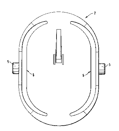
Figure 2 is a top view of the second part of the
pivotable joint;
Figure 3 is a transverse sectional view through the
second part of the pivotable joint; and
Figure ~ is a longitudinal sectional view through the
assembled pivotable joint.
- 2 -

2~2~
Detailed Description of Preferred Embodiments
The pivotable joint of the invention comprises a first
part 1 and a second part 2, which are made of plastic. The
first part 1 is provided with pivot bores 3 on opposite
sides, only one of which is shown in the drawing. Assembly
grooves ox guide grooves 4 which lead to the pivot bores 3
are provided in first part 1 to facilitate assembly of the
parts.
The second part 2 is provided with elastic pivots 5.
As can be seen most clearly in Figure 2, second part 2
comprises a generally flat central portion and resilient
arms attached to the ends of the central portion so that
they extend along opposite sides of the second part. The
pivot pins 5 are symmetrically mounted on these arms on
opposite sides of the second part 2. Due to the
construction of the illustrated embodiment, the pivot pins
are displaceable essentially only in the axial direction.
The axial deformation or displacement of elastic pivot pins
5 is limited by abutments 6 provided for that purpose. Thus
the elastic pivots 5 are protected against overstress and
destruction.
The second part 2 also is provided with a mounting
member 7 for a control linkage by means of which the second
part can be caused to pivot in order to aæsume desired
positions in operation. In the illustrated preferred
embodiment, a throttle valve abutment 8 is provided on the
first part 1 to limit the pivoting of second part 2, and
thereby prevent complete closure of the throttle valve.
The foregoing description and examples have been set
forth merely to illustrate the invention and are not
intended to be limiting. Since modifications of the
described embodiments incorporating the spirit and substance
o~ the invention may occur to persons skilled in the art,
the invention should be construed broadly to include all
variations falling within the scope of the appended claims
and equivalents thereof.

Representative Drawing
A single figure which represents the drawing illustrating the invention.
Administrative Status

2024-08-01:As part of the Next Generation Patents (NGP) transition, the Canadian Patents Database (CPD) now contains a more detailed Event History, which replicates the Event Log of our new back-office solution.

Please note that "Inactive:" events refers to events no longer in use in our new back-office solution.

For a clearer understanding of the status of the application/patent presented on this page, the site Disclaimer , as well as the definitions for Patent , Event History , Maintenance Fee  and Payment History  should be consulted.

Event History

Description Date
Inactive: IPC from MCD 2006-03-11
Application Not Reinstated by Deadline 1998-11-05
Time Limit for Reversal Expired 1998-11-05
Deemed Abandoned - Failure to Respond to Maintenance Fee Notice 1997-11-05
Application Published (Open to Public Inspection) 1993-05-06

Abandonment History

Abandonment Date Reason Reinstatement Date
1997-11-05
Owners on Record

Note: Records showing the ownership history in alphabetical order.

Current Owners on Record
FILTERWERK MANN & HUMEL GMBH
Past Owners on Record
MANFRED MUELLER
MANFRED WINTER
Past Owners that do not appear in the "Owners on Record" listing will appear in other documentation within the application.
Documents

To view selected files, please enter reCAPTCHA code :


To view images, click a link in the Document Description column. To download the documents, select one or more checkboxes in the first column and then click the "Download Selected in PDF format (Zip Archive)" or the "Download Selected as Single PDF" button.

List of published and non-published patent-specific documents on the CPD .

If you have any difficulty accessing content, you can call the Client Service Centre at 1-866-997-1936 or send them an e-mail at CIPO Client Service Centre.


Document
Description 
Date
(yyyy-mm-dd) 
Number of pages   Size of Image (KB) 
Claims 1993-05-05 2 48
Drawings 1993-05-05 3 37
Abstract 1993-05-05 1 19
Descriptions 1993-05-05 3 122
Representative drawing 1998-11-04 1 8
Courtesy - Abandonment Letter (Maintenance Fee) 1997-12-02 1 185
Fees 1996-10-21 1 59
Fees 1995-10-12 1 37
Fees 1994-10-13 1 56