Sélection de la langue

Search

Sommaire du brevet 2082254 

Énoncé de désistement de responsabilité concernant l'information provenant de tiers

Une partie des informations de ce site Web a été fournie par des sources externes. Le gouvernement du Canada n'assume aucune responsabilité concernant la précision, l'actualité ou la fiabilité des informations fournies par les sources externes. Les utilisateurs qui désirent employer cette information devraient consulter directement la source des informations. Le contenu fourni par les sources externes n'est pas assujetti aux exigences sur les langues officielles, la protection des renseignements personnels et l'accessibilité.

Disponibilité de l'Abrégé et des Revendications

L'apparition de différences dans le texte et l'image des Revendications et de l'Abrégé dépend du moment auquel le document est publié. Les textes des Revendications et de l'Abrégé sont affichés :

  • lorsque la demande peut être examinée par le public;
  • lorsque le brevet est émis (délivrance).
(12) Demande de brevet: (11) CA 2082254
(54) Titre français: JOINT PIVOTANT
(54) Titre anglais: PIVOTABLE JOINT
Statut: Morte
Données bibliographiques
(51) Classification internationale des brevets (CIB):
  • F02D 9/10 (2006.01)
  • E05D 7/10 (2006.01)
  • F02D 9/02 (2006.01)
  • F16K 27/02 (2006.01)
(72) Inventeurs :
  • MUELLER, MANFRED (Allemagne)
  • WINTER, MANFRED (Allemagne)
(73) Titulaires :
  • FILTERWERK MANN & HUMEL GMBH (Allemagne)
(71) Demandeurs :
(74) Agent: BORDEN LADNER GERVAIS LLP
(74) Co-agent:
(45) Délivré:
(22) Date de dépôt: 1992-11-05
(41) Mise à la disponibilité du public: 1993-05-06
Licence disponible: S.O.
(25) Langue des documents déposés: Anglais

Traité de coopération en matière de brevets (PCT): Non

(30) Données de priorité de la demande:
Numéro de la demande Pays / territoire Date
G 91 13 727.6 Allemagne 1991-11-05

Abrégés

Abrégé anglais


Abstract of the Disclosure
A pivotable joint including a first part provided with
pivot bores and a second part with resiliently mounted pivot
pins received in said pivot bores such that the second part
is pivotably mounted in a desired assembled position. The
first part has a closed tubular cross section and may be a
section of the intake manifold of an internal combustion
engine. The resiliently mounted pivot pins are
symmetrically mounted on opposite sides of the second part,
which may be a throttle valve. The pivot pins are
elastically displaceable axially during assembly of the
first and second parts such that they snap resiliently into
the pivot bores of the first part when the second part
reaches the desired assembled position.

Revendications

Note : Les revendications sont présentées dans la langue officielle dans laquelle elles ont été soumises.


THE EMBODIMENTS OF THE INVENTION IN WHICH AN EXCLUSIVE
PROPERTY OR PRIVILEGE IS CLAIMED ARE DEFINED AS FOLLOWS:


1. A pivotable joint comprising a first part provided
with pivot bores and a second part with resiliently mounted
pivot pins received in said pivot bores such that said
second part is pivotably mounted in a desired assembled
position relative to said first part, wherein said first
part has a closed tubular cross section, and wherein said
pivot pins of said second part are elastically displaceable
during assembly of said first and second parts and snap
resiliently into the pivot bores of said first part when
said second part reaches said desired assembled position.

2. A pivotable joint according to claim 1, wherein
said first part comprises a section of an intake manifold of
an internal combustion engine, and said second part is a
throttle valve disposed in said intake manifold.

3. A pivotable joint according to claim 1, wherein
stop means are provided on said second part for limiting the
resilient displacement of said pivot pins.

4. A pivotable joint according to claim 1, wherein
assembly grooves are provided on said first part for guiding
said resiliently mounted pivot pins of said second part to
said pivot bores of said first part during assembly of said
first and second parts.

5. A pivotable joint according to claim 1, further
comprising a mounting member formed on said second part for
connecting a control linkage for controlling pivoting of
said second part relative to said first part.

6. A pivotable joint according to claim 1, wherein
said elastic pivots are attached to opposite sides of said
second part.

- 4 -


7. A pivotable joint according to claim 6, wherein
said elastic pivots are symmetrically attached to opposite
sides of said second part.

8. A pivotable joint according to claim 1, wherein
said elastic pivots of said second part are deformable only
in the axial direction.

- 5 -

Description

Note : Les descriptions sont présentées dans la langue officielle dans laquelle elles ont été soumises.


21D~22~


PIVOTABLE JOINT
Background of the Invention
This invention relates to a pivotable joint in which a
first part is provided with pivot bores and a second part
with elastic mounting pins or pivot pins.
5Pivotable joints of this general type are known, e.g.,
in boxes for music cassettes. However, if it is desired to
use such pivotable joints, for example, in intake manifolds
with throttle valves, it is disadvantageous that the passage
cross section would have to be made elastic. This would
certainly be difficult and expensive. A housing could also
be provided which could be divided and then reassembled in
order to mount the throttle valve. This is, however, costly
to manufacture, and it would make the pivotable joint
expensive. Another possibility would be to mount the
throttle valve on a continuous shaft extended through pivot
bores. This, however, would be difficult to assemble and
would make it necessary afterward to seal up the intake
manifold.

Summary o~ the Invention
It is therefore the object o~ the invention to improve
a pivotable joint of the kind described above by providing
a pivotable joint which is simple, inexpensive and easy-to-
assemble and disassemble.
25These and other objects o~ the invention are achieved
by providing a pivotable joint comprising a first part with
pivot bores and a second part with pivot pins inserted in

-- 1 --

2~822~

the pivot bores of the first part, in which the first part
with the pivot bores has an unbroken tubular cross section,
the second part has resiliently mounted pivot pins which
during assembly deform or shift from their original
positions, and when the second part reaches the desired
assembled position relative to the first part, the elastic
pivot pins snap resiliently into the pivot bores of the
first part.
~n a particularly preferred embodiment of the
lo invention, the first part comprises a section of an intake
manifold of an internal combustion engine and the second
part is a throttle valve disposed in the intake manifold.
When the pivot pins snap into place, they reassume
their original positions, and with the aid of the overall
stability of the second part they resist accidental
dislodging~ on the other hand, this "locking up" due to the
inherent elasticity of the material--plastic, for example--
is so pliant that, by applying pressure in the right
direction against the pivot mounting, the second part can be
removed and reinstalled as often as desired.
Further advantageous features of preferred embodiments
of the invention will appear from a consideration of the
following detailed description of preferred embodiments.

Brief Description of the Drawinas
The invention will be described in further detail
hereinafter with reference to an illustrative preferred
embodiment shown in the aacompanying drawings in which:
Figure 1 is a sectional view through the first part of
the pivotable joint;
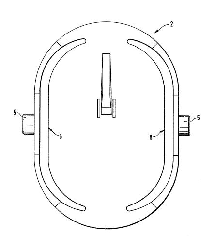
Figure 2 is a top view of the second part of the
pivotable joint;
Figure 3 is a transverse sectional view through the
second part of the pivotable joint; and
Figure ~ is a longitudinal sectional view through the
assembled pivotable joint.
- 2 -

2~2~

Detailed Description of Preferred Embodiments
The pivotable joint of the invention comprises a first
part 1 and a second part 2, which are made of plastic. The
first part 1 is provided with pivot bores 3 on opposite
sides, only one of which is shown in the drawing. Assembly
grooves ox guide grooves 4 which lead to the pivot bores 3
are provided in first part 1 to facilitate assembly of the
parts.
The second part 2 is provided with elastic pivots 5.
As can be seen most clearly in Figure 2, second part 2
comprises a generally flat central portion and resilient
arms attached to the ends of the central portion so that
they extend along opposite sides of the second part. The
pivot pins 5 are symmetrically mounted on these arms on
opposite sides of the second part 2. Due to the
construction of the illustrated embodiment, the pivot pins
are displaceable essentially only in the axial direction.
The axial deformation or displacement of elastic pivot pins
5 is limited by abutments 6 provided for that purpose. Thus
the elastic pivots 5 are protected against overstress and
destruction.
The second part 2 also is provided with a mounting
member 7 for a control linkage by means of which the second
part can be caused to pivot in order to aæsume desired
positions in operation. In the illustrated preferred
embodiment, a throttle valve abutment 8 is provided on the
first part 1 to limit the pivoting of second part 2, and
thereby prevent complete closure of the throttle valve.
The foregoing description and examples have been set
forth merely to illustrate the invention and are not
intended to be limiting. Since modifications of the
described embodiments incorporating the spirit and substance
o~ the invention may occur to persons skilled in the art,
the invention should be construed broadly to include all
variations falling within the scope of the appended claims
and equivalents thereof.
Dessin représentatif
Une figure unique qui représente un dessin illustrant l'invention.
États administratifs

Pour une meilleure compréhension de l'état de la demande ou brevet qui figure sur cette page, la rubrique Mise en garde , et les descriptions de Brevet , États administratifs , Taxes périodiques et Historique des paiements devraient être consultées.

États administratifs

Titre Date
Date de délivrance prévu Non disponible
(22) Dépôt 1992-11-05
(41) Mise à la disponibilité du public 1993-05-06
Demande morte 1998-11-05

Historique d'abandonnement

Date d'abandonnement Raison Reinstatement Date
1997-11-05 Taxe périodique sur la demande impayée

Historique des paiements

Type de taxes Anniversaire Échéance Montant payé Date payée
Le dépôt d'une demande de brevet 0,00 $ 1992-11-05
Enregistrement de documents 0,00 $ 1993-12-03
Taxe de maintien en état - Demande - nouvelle loi 2 1994-11-07 100,00 $ 1994-10-14
Taxe de maintien en état - Demande - nouvelle loi 3 1995-11-06 100,00 $ 1995-10-13
Taxe de maintien en état - Demande - nouvelle loi 4 1996-11-05 100,00 $ 1996-10-22
Titulaires au dossier

Les titulaires actuels et antérieures au dossier sont affichés en ordre alphabétique.

Titulaires actuels au dossier
FILTERWERK MANN & HUMEL GMBH
Titulaires antérieures au dossier
MUELLER, MANFRED
WINTER, MANFRED
Les propriétaires antérieurs qui ne figurent pas dans la liste des « Propriétaires au dossier » apparaîtront dans d'autres documents au dossier.
Documents

Pour visionner les fichiers sélectionnés, entrer le code reCAPTCHA :


Pour visualiser une image, cliquer sur un lien dans la colonne description du document. Pour télécharger l'image (les images), cliquer l'une ou plusieurs cases à cocher dans la première colonne et ensuite cliquer sur le bouton "Télécharger sélection en format PDF (archive Zip)" ou le bouton "Télécharger sélection (en un fichier PDF fusionné)".

Liste des documents de brevet publiés et non publiés sur la BDBC .

Si vous avez des difficultés à accéder au contenu, veuillez communiquer avec le Centre de services à la clientèle au 1-866-997-1936, ou envoyer un courriel au Centre de service à la clientèle de l'OPIC.


Description du
Document 
Date
(yyyy-mm-dd) 
Nombre de pages   Taille de l'image (Ko) 
Page couverture 1993-05-06 1 17
Abrégé 1993-05-06 1 22
Revendications 1993-05-06 2 55
Dessins 1993-05-06 3 41
Dessins représentatifs 1998-11-05 1 9
Description 1993-05-06 3 138
Taxes 1996-10-22 1 59
Taxes 1995-10-13 1 37
Taxes 1994-10-14 1 56