Language selection

Search

Patent 2088648 Summary

Third-party information liability

Some of the information on this Web page has been provided by external sources. The Government of Canada is not responsible for the accuracy, reliability or currency of the information supplied by external sources. Users wishing to rely upon this information should consult directly with the source of the information. Content provided by external sources is not subject to official languages, privacy and accessibility requirements.

Claims and Abstract availability

Any discrepancies in the text and image of the Claims and Abstract are due to differing posting times. Text of the Claims and Abstract are posted:

  • At the time the application is open to public inspection;
  • At the time of issue of the patent (grant).
(12) Patent: (11) CA 2088648
(54) English Title: LIGHT FIXTURE FOR MOUNTING TO A CEILING, WALL OR THE LIKE
(54) French Title: APPAREIL D'ECLAIRAGE POUR MONTAGE AU PLAFOND, AU MUR OU AUTRES SURFACES DU GENRE
Status: Expired
Bibliographic Data
Abstracts

English Abstract


The disclosure herein describes a light fixture
for mounting to a ceiling, wall or the like which
comprises a pot having a peripheral edge abutting the
area adjacent a hole made in the ceiling or wall. A hook
and a bolt extending through appropriate openings in the
inner wall and the side wall of the pot cooperate to
secure the pot to the ceiling. Rotating the bolt causes
the hook to move into an abuting engagement with the rear
surface of the ceiling, the latter thus being contacted,
on the outside, by the peripheral edge of the pot and, on
the inside, by that portion of the hook engaging the rear
surface of the ceiling.


Claims

Note: Claims are shown in the official language in which they were submitted.


-6-

The embodiments of the invention in which an
exclusive property or privilege is claimed are defined as
follows:

1. A light fixture for mounting into an
opening made in a ceiling, wall or the like defining a
front surface and a rear surface, said fixture
comprising:
a pot adapted to be received rearwardly of
said ceiling, said pot having an inner wall and a side
wall; said side wall having an outer peripheral flange
adapted to bear against said front surface adjacent said
opening; said side wall defining slot means therein;
a hook consisting of an elongated body
having a main portion adapted to extend through said slot
means substantially parallel to said side wall of said
pot; said body having a first end portion bent to extend
substantially parallel to and rearwardly of said inner
wall of said pot and a second end portion bent to extend
substantially parallel to and rearwardly of said rear
surface of said ceiling; said first end portion defining
a threaded hole therethrough;
a bolt having a head and an elongated
threaded stem adapted to extend through said opening of
said inner wall of said pot and to engage said threaded
hole of said first end portion of said hook whereby
rotation of said bolt causes said first end portion to
move longitudinally along said stem of said bolt and said


-7-

second end portion to move to bear against said rear
surface of said ceiling to thereby secure said light
fixture to said ceiling.

2. A light fixture as defined in claim 1,
wherein said slot means consist of a pair of vertically
aligned slots to allow portions of said main portion of
said hook to extend frontwardly and rearwardly of said
side wall.

3. A light fixture as defined in claim 2,
wherein said body of said hook has a rectangular cross-
section and a width slightly smaller than that of said
slots.

4. A light fixture as defined in claim 3,
wherein said second end portion has an enlarged width
relative to that of remaining portions of the hook and
wherein one of said slots has an enlarged lower section
to correspondly receive therethrough said portion having
a greater width.


5. A light fixture as defined in claim 2,
wherein said main portion of said hook comprises an upper
part, and intermediate part and a lower part; said upper
and lower parts extending rearwardly of said side wall
when mounted to said pot and said intermediate part
extending within said pot.


Description

Note: Descriptions are shown in the official language in which they were submitted.


- 1- 2088648


FIBLD OF THE lNV~ lON
The present invention pertains to a light
fixture for mounting to a ceiling, wall or the like in
which a hole has been made to receive the fixture.


BACRGROUND OF THE lNV~N.lON
There are various fastening devices to mount a
light fixture, in the form of a pot, to a ceiling or the
like. With those using a spring arrangement, the fixing
is accomplished inside the hole. Other systems require
a metallic plate inside the ceiling which results in an
electrician to work inside the ceiling to carry out the
mounting operation. Other devices require the provision
of a lath to which the pot is fixed. It has been found
that, in most cases, to secure the pot to the ceiling
often causes some damage to the material of the ceiling.


OBJECTS AND STATEMENT OF THE l~v~NlION
It is an object of the present invention to
overcome present problems of existing systems for fixing
a light fixture to a ceiling, wall or the like.


It is also an object of the present invention
to provide a mounting device which is easy to use and

which may be installed independently of the thickness of
the ceiling or wall.

~ - 2 - 2088648


This is achieved by providing a light fixture
which comprises:
- a pot, having an inner wall and a side wall,
adapted to be received rearwardly of the ceiling, the
side wall having an outer peripheral flange adapted to
bear against the front surface adjacent the opening; the
side wall defining slot means therein;
- a hook consisting of an elongated body
having a main portion adapted to extend through the slot
means substantially parallel to the side wall of the pot,
the body having a first end portion bent to extend
substantially parallel to the inner wall of the pot and
a second end portion bent to extend substantially
parallel to and rearwardly of the rear surface of the
ceiling; the first end portion defining a threaded hole
therethrough;
- a bolt having a head and an elongated
threaded stem adapted to extend through the opening of
the inner wall and to engage the threaded hole of the
first end portion of the hook whereby rotation of the
bolt causes the first end portion to move longitudinally
along the stem of the bolt and the second end portion to
move to bear against the rear surface of the ceiling to
thereby secure the light fixture to the ceiling.


In one form of the invention, the side wall of
the pot is provided with two vertically aligned slots
through which extend upper and lower parts of the hook.

2088648
_ - 3


In a further form of the invention, the lower
bent end portion of the hook as an enlarged width
relative to that of the rest of the hook to augment the
abutting function.


Other objects and further scope of
applicability of the present invention will become
apparent from the detailed description given hereinafter.
It should be understood, however, that this detailed
description, while indicating preferred embodiments of
the invention, is given by way of illustration only,
since various changes and modifications within the spirit
and scope of the invention will become apparent to those
skilled in the art.


IN THE DRAWINGS
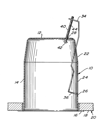
Figure 1 is a cross-sectional view of a pot
forming part of the light fixture made in accordance with
the present invention;
Figure 2 is a perspective view of a hook
forming part of the light fixture of the present
invention;
Figures 3 and 4 show successive operations for
securing the light fixture to a ceiling.


DESCRIPTION OF PREFERRED EMBODIMENTS
Referring to figure 1, there is shown a pot 10
having an inner wall 12 and a sidewall 14, the latter

20B864 8


having a peripheral outer flange 16 which is adapted to
bear against the front surface 18 of a ceiling 20.


The side wall 14 displays a pair of slots 22
and 24 vertically aligned with respect to one another,
S the lower slot having an enlarged lower section 26. As
can be seen in figure 3, the inner wall 12 has an opening
28.


Referring to figure 2, a hook, generally
denoted 30, defines an elongated rectangular body 32
having, at respective opposite ends thereof, a first bent
portion 34 and a second bent portion 36, both extending
substantially perpendicular to the main portion of body
32, which consists of an upper part 32a, an intermediate
part 32b and a lower part 32c.


Referring to figure 3, the light fixture also
comprises a bolt 40 having a head 42 and an elongated
threaded stem portion 44 which extends through the
opening 28 of the inner wall of the pot. This portion 44
threadingly engages hole 38 of the hook.


To secure the pot into the opening of the
ceiling, the bent portion 34 is inserted into slot 22
while bolt 40 is inserted in opening 28 and is threadedly
engaged in hole 38 of the bent portion 34. The lower
bent portion 36 is inserted into slot 26 so that parts

208~648
-- 5


32c and 32a of the hook lie rearwardly of the wall 14 of
the pot while part 32b extends inside the pot. The bolt
is rotated until the hook reaches the position shown in
figure 4 where the enlarged lower bent portion 36 abuts
the rear surface of the ceiling, thus securing the pot in
the ceiling opening.


Although the invention has been described above
with in relation to one specific form, it will be evident
to a person skilled in the art that it may be modified
and refined in various ways. It is therefore wished to
have it understood that the present invention should not
be limited in scope, except by the terms of the following
claims.


Representative Drawing
A single figure which represents the drawing illustrating the invention.
Administrative Status

For a clearer understanding of the status of the application/patent presented on this page, the site Disclaimer , as well as the definitions for Patent , Administrative Status , Maintenance Fee  and Payment History  should be consulted.

Administrative Status

Title Date
Forecasted Issue Date 1995-03-28
(22) Filed 1993-02-02
(41) Open to Public Inspection 1994-08-03
Examination Requested 1994-10-24
(45) Issued 1995-03-28
Expired 2013-02-04

Abandonment History

There is no abandonment history.

Payment History

Fee Type Anniversary Year Due Date Amount Paid Paid Date
Application Fee $0.00 1993-02-02
Maintenance Fee - Application - New Act 2 1995-02-02 $100.00 1994-12-19
Maintenance Fee - Patent - New Act 3 1996-02-02 $100.00 1996-01-05
Maintenance Fee - Patent - New Act 4 1997-02-03 $100.00 1997-01-20
Maintenance Fee - Patent - New Act 5 1998-02-02 $150.00 1998-01-21
Maintenance Fee - Patent - New Act 6 1999-02-02 $150.00 1998-12-03
Maintenance Fee - Patent - New Act 7 2000-02-02 $150.00 1999-12-08
Maintenance Fee - Patent - New Act 8 2001-02-02 $150.00 2000-12-07
Maintenance Fee - Patent - New Act 9 2002-02-04 $150.00 2001-12-04
Maintenance Fee - Patent - New Act 10 2003-02-03 $200.00 2003-01-27
Maintenance Fee - Patent - New Act 11 2004-02-02 $250.00 2004-01-19
Maintenance Fee - Patent - New Act 12 2005-02-02 $250.00 2004-12-06
Maintenance Fee - Patent - New Act 13 2006-02-02 $250.00 2005-12-21
Maintenance Fee - Patent - New Act 14 2007-02-02 $250.00 2007-02-01
Maintenance Fee - Patent - New Act 15 2008-02-04 $450.00 2008-01-08
Maintenance Fee - Patent - New Act 16 2009-02-02 $450.00 2009-01-30
Maintenance Fee - Patent - New Act 17 2010-02-02 $450.00 2010-01-26
Registration of a document - section 124 $100.00 2010-06-17
Registration of a document - section 124 $100.00 2010-06-21
Maintenance Fee - Patent - New Act 18 2011-02-02 $450.00 2010-11-12
Registration of a document - section 124 $100.00 2011-06-30
Maintenance Fee - Patent - New Act 19 2012-02-02 $450.00 2011-12-20
Owners on Record

Note: Records showing the ownership history in alphabetical order.

Current Owners on Record
ECLAIRAGE CONTRASTE M.L. INC.
Past Owners on Record
LECLUZE, MICHEL
Past Owners that do not appear in the "Owners on Record" listing will appear in other documentation within the application.
Documents

To view selected files, please enter reCAPTCHA code :


To view images, click a link in the Document Description column. To download the documents, select one or more checkboxes in the first column and then click the "Download Selected in PDF format (Zip Archive)" or the "Download Selected as Single PDF" button.

List of published and non-published patent-specific documents on the CPD .

If you have any difficulty accessing content, you can call the Client Service Centre at 1-866-997-1936 or send them an e-mail at CIPO Client Service Centre.


Document
Description 
Date
(yyyy-mm-dd) 
Number of pages   Size of Image (KB) 
Abstract 1995-03-28 1 18
Description 1995-03-28 5 140
Claims 1995-03-28 2 62
Drawings 1995-03-28 2 51
Cover Page 1995-03-28 1 15
Representative Drawing 1999-06-28 1 13
Fees 2003-01-27 1 39
Fees 1999-12-08 1 43
Fees 1998-12-03 1 50
Fees 2001-12-04 1 39
Fees 2004-01-19 1 34
Fees 1998-01-21 1 45
Fees 2000-12-07 1 40
Prosecution Correspondence 1994-10-25 3 98
Office Letter 1994-11-10 1 55
PCT Correspondence 1995-01-16 1 37
Fees 2004-12-06 1 33
Assignment 2011-06-30 37 1,921
Fees 2005-12-21 1 51
Fees 2007-02-01 1 44
Fees 2008-01-08 1 44
Fees 2009-01-30 1 46
Assignment 2010-06-17 2 74
Assignment 2010-06-21 59 2,830
Fees 1997-01-20 1 55
Fees 1996-01-05 1 44
Fees 1994-12-19 1 46