Language selection

Search

Patent 2105946 Summary

Third-party information liability

Some of the information on this Web page has been provided by external sources. The Government of Canada is not responsible for the accuracy, reliability or currency of the information supplied by external sources. Users wishing to rely upon this information should consult directly with the source of the information. Content provided by external sources is not subject to official languages, privacy and accessibility requirements.

Claims and Abstract availability

Any discrepancies in the text and image of the Claims and Abstract are due to differing posting times. Text of the Claims and Abstract are posted:

  • At the time the application is open to public inspection;
  • At the time of issue of the patent (grant).
(12) Patent: (11) CA 2105946
(54) English Title: CAKE RACK
(54) French Title: VOLETTE A GATEAUX
Status: Deemed expired
Bibliographic Data
(51) International Patent Classification (IPC):
  • A47B 55/02 (2006.01)
  • A21B 3/15 (2006.01)
  • A47G 19/02 (2006.01)
(72) Inventors :
  • LOCKETT, ELLA-WINN M. (United States of America)
(73) Owners :
  • LOCKETT, ELLA-WINN M. (United States of America)
(71) Applicants :
(74) Agent: OSLER, HOSKIN & HARCOURT LLP
(74) Associate agent:
(45) Issued: 2000-04-11
(22) Filed Date: 1993-09-10
(41) Open to Public Inspection: 1995-03-11
Examination requested: 1994-01-05
Availability of licence: N/A
(25) Language of filing: English

Patent Cooperation Treaty (PCT): No

(30) Application Priority Data: None

Abstracts

English Abstract


ABSTRACT OF THE DISCLOSURE

The present invention includes a wire cake rack for supporting
either tubular or rectangular cakes while cooling. The wire cake
rack can be either a round cake rack for supporting tubular cakes,
e.g. Bundt cakes or a rectangular cake rack for supporting
rectangular cakes, e.g. pound cakes. The round cake rack is made
with sides in the shape of an open top cylinder manufactured
integrally with a bottom that is concentric with the sides, with
the bottom having a greater diameter than the sides. Handles are
included on diametrically opposite edges of the bottom. The
rectangular cake rack is made with sides in the shape of an open
top rectangular box manufactured integrally with a bottom that is
axially aligned with the sides. The bottom extends a predetermined
distance beyond the sides and includes handles on the two edges of
the bottom that are longer than the other two edges of the bottom.
With both embodiments, the cake racks can be stacked together
because the rack sides are made of slightly different diameters so
that they can stack inside of each other.


Claims

Note: Claims are shown in the official language in which they were submitted.


THE EMBODIMENTS OF THE INVENTION IN WHICH AN EXCLUSIVE
PROPERTY OR PRIVILEGE IS CLAIMED ARE DEFINED AS FOLLOWS:


1. A cake rack for use in the cooling of cakes after
baking, comprising: a flat bottom surface having a major
diameter, said flat bottom surface adapted to support a cake;
and a side barrier having a minor diameter less than said
major diameter, said side barrier being integrally attached to
a top portion of said flat bottom surface and disposed at a
right angle thereto, whereby a receptacle is formed which is
open at one end and includes a flange extending outside said
side barrier:
said flat bottom surface having an edgeward periphery;
said flat bottom surface having a first and second handle:
said first handle being attached on said edgeward periphery of
said flat bottom surface, said second handle being attached on
said edgeward periphery of said flat bottom surface in a
position substantially opposite to said first handle, said
first and second handles extending outward from said edgeward
periphery in a plane substantially parallel with said flat
bottom surface;
said flat bottom surface having at least three surface
elevating legs, said surface elevating legs attached
substantially isometrically along said edgeward periphery in
a plane downwardly angled from the top portion of said flat
bottom surface and said side barrier:
said side barrier comprising a plurality of upright
pillars and a plurality of peripheral rails:
said upright pillars vertically extending from said flat
bottom surface, said upright pillars spaced substantially
equidistantly from each other about a periphery of said side
barrier, each of said upright pillars being substantially
dimensionally identical to each of the other upright pillars;
each of said peripheral rails positioned in a plane
substantially parallel to said flat bottom surface, each of
said peripheral rails being substantially dimensionally
identical with each of the other peripheral rails, each of said


peripheral rails being planarly equidistant from each adjacent
peripheral rail;
said plurality of pillars connected to said plurality of
peripheral rails to form said side barrier.
2. The cake rack according to claim 1, said flat bottom
surface and said side barrier being round.
3. The cake rack according to claim 1, said flat bottom
surface and said side barrier being rectangular.

Description

Note: Descriptions are shown in the official language in which they were submitted.


CARE RACK
BACKGROUND OF TEiE INVENTION
1. FTELD OF THE INVENTION
The present invention relates to one piece wire cake racks for
cooling tubular or rectangular bakery products such as cakes.
2. DESCRIPTION OF THE PRIOR ~.RT
The prior art cake cooling racks have inherent deficiencies.
For example, there are well known cake racks comprising little or
no more than a flat wire surface. These cake racks have the
deficiency that they do not support the sides of the cake and,
therefore, the cake is able to slide off of the cake rack onto the
floor if the cake pan is not removed from the cake with precisely
the right manner.
Heretofore, it has been proposed to provide devices for
supporting a tube cake pan in an inverted position during the
cooling of the cake. However, these devices do not provide for the
tube cakes to be cooled independent of the cake pan.
U.S. Patent No. 2,777,308 issued January 15, 1957 to Robert W.
Roberts discloses a combination cake plate and cooler for tube
cakes that has extensions leading up from the cake plate for
supporting the inner ring of a tube cake pan and the outer edge of
a tube cake pan while a tube cake is cooling. The tube cake pan is
supported in an inverted position during the cooling process and
the tube cake is then removed from the cake pan and supported on
the integral cake plate for cutting and serving of the tube. cake.
None of the above inventions and patents, taken either singly
or incombination, is seen to describe the instant invention as
claimed.
SUMIH~rR7C OF THE INVENTION


CA 02105946 1998-04-22
sliding off the cake rack due to an improved wire rack
manufactured in one piece.
Furthermore, I propose to provide wire cake racks that are
able to be stacked for storage.
The instant invention seeks to provide a wire cake rack
for cooling either rectangular, square, or tubular cakes.
From the above, it will be apparent that the instant
structure provides improved elements and arrangements
described, which is inexpensive, dependable and fully effective
in accomplishing its intended purposes.
In accordance with an embodiment of the present invention
there is provided a cake rack for use in the cooling of cakes
after baking. The cake rack comprises: a flat bottom surface
having a major diameter, the flat bottom surface adapted to
support a cake: and a side barrier having a minor diameter less
than the major diameter, the side barrier being integrally
attached to a top portion of the flat bottom surface and
disposed at a right angle thereto, whereby a receptacle is
formed which is open at one end and includes a flange extending
outside said side barrier; the flat bottom surface having an
edgeward periphery. The flat bottom surface has a first and
second handle. The first handle is attached on the edgeward
periphery of the flat bottom surface and the second handle is
attached on the edgeward periphery of the flat bottom surface
in a position substantially opposite to the first handle. The
first and second handles extend outward from the edgeward
periphery in a plane substantially parallel with the flat
bottom surface. The flat bottom surface has at least three
surface elevating legs. The surface elevating legs are
attached substantially isometrically along said edgeward
periphery in a plane downwardly angled from the top portion of
the flat bottom surface and the side barrier. The side barrier
comprises a plurality of upright pillars and a plurality of
2


CA 02105946 1998-04-22
peripheral rails. The upright pillars vertically extend from
the flat bottom surface and the upright pillars are spaced
substantially equidistantly from each other about a periphery
of the side barrier. Each of the upright pillars is
substantially dimensionally identical to each of the other
upright pillars. Each of the peripheral rails is positioned
in a plane substantially parallel to the flat bottom surface.
Each of the peripheral rails is substantially dimensionally
identical with each of the other peripheral rails and each of
the peripheral rails is planarly equidistant from each adjacent
peripheral rail. The plurality of pillars are connected to the
plurality of peripheral rails to form the side barrier.
These and other features of the present invention will
become readily apparent upon further review of the following
specification and drawings.
BRIEF DEBCRIPTION OF THE DRAWINGS
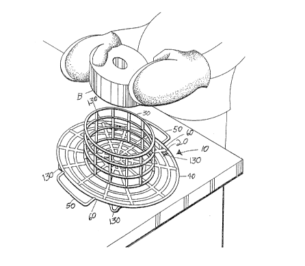
Fig. 1 is a perspective view of one embodiment of the
present invention:
Fig. 2 is a top plan view of a second embodiment thereof;
Fig. 3 is a schematic view showing the stacking means of
the first embodiment; and
Fig. 4 is a schematic view showing the stacking means of
the second embodiment.
Similar reference characters denote corresponding features
consistently throughout the attached drawings.
DETAILED DESCRIPTION OF THE PREFERRED EMBODIMENTB
The present invention comprises a wire cake rack 10 for
supporting either tubular, square, or rectangular cakes while
they cool. Referring to Fig. 1, the wire cake rack 10 includes
a round cake rack 20 for supporting tubular cakes, e.g. Bundt
cakes B. The round cake rack 20 is made with sides 30 in the
shape of an open top cylinder that are manufactured integrally
with a bottom 40 that
2a

JL
defines a greater diameter than the diameter of the sides 30. The
bottom 40 will be seen to include handles 50 on diametrically
opposite edges 60 of the bottom 40 as well as feet 130 attached to
four points of the underside of the bottom 40.
All of the above-described rack components will be understood
to be of wire construction with the rack 20 and sides presenting a
unanimous configuration allowing for adept support together with
sufficient cooling ability.
Referring now to Fig. 2, the wire cake rack 10 defines a
rectangular cake rack 70 for supporting rectangular cakes, e.g.
sheet or pound cakes. The rectangular cake rack 70 is made with
sides 80 in the shape of an open top rectangular box and is
manufactured integrally with a bottom 90 that is axially aligned
with the sides 80. The bottom 90 includes handles 100 on the two
edges 110 of the bottom 90 that are longer than the other two edges
120 of the bottom 90.
Referring now to Fig. 3, the round wire cake racks 20 can be
stacked together. The wire racks 20 are made of slightly different
diameters D so that they can stack inside of each other.
Similarly,.referring to Fig. 4, the rectangular wire racks 70 are
made of slightly different axial dimensions L and W so that they
can stack inside of each other.
It is to be understood that the present invention is not~
limited to the sole embodiments within the scope of the following.
claims.
3

Representative Drawing
A single figure which represents the drawing illustrating the invention.
Administrative Status

For a clearer understanding of the status of the application/patent presented on this page, the site Disclaimer , as well as the definitions for Patent , Administrative Status , Maintenance Fee  and Payment History  should be consulted.

Administrative Status

Title Date
Forecasted Issue Date 2000-04-11
(22) Filed 1993-09-10
Examination Requested 1994-01-05
(41) Open to Public Inspection 1995-03-11
(45) Issued 2000-04-11
Deemed Expired 2007-09-10

Abandonment History

There is no abandonment history.

Payment History

Fee Type Anniversary Year Due Date Amount Paid Paid Date
Application Fee $0.00 1993-09-10
Request for Examination $200.00 1994-01-05
Maintenance Fee - Application - New Act 2 1995-09-11 $50.00 1995-08-21
Maintenance Fee - Application - New Act 3 1996-09-10 $50.00 1996-08-16
Maintenance Fee - Application - New Act 4 1997-09-10 $50.00 1997-08-27
Maintenance Fee - Application - New Act 5 1998-09-10 $75.00 1998-04-08
Maintenance Fee - Application - New Act 6 1999-09-10 $75.00 1999-09-01
Final Fee $150.00 2000-01-14
Maintenance Fee - Patent - New Act 7 2000-09-11 $75.00 2000-08-21
Maintenance Fee - Patent - New Act 8 2001-09-10 $75.00 2001-04-26
Maintenance Fee - Patent - New Act 9 2002-09-10 $75.00 2002-08-26
Maintenance Fee - Patent - New Act 10 2003-09-10 $100.00 2003-08-14
Maintenance Fee - Patent - New Act 11 2004-09-10 $125.00 2004-09-07
Maintenance Fee - Patent - New Act 12 2005-09-12 $125.00 2005-08-16
Owners on Record

Note: Records showing the ownership history in alphabetical order.

Current Owners on Record
LOCKETT, ELLA-WINN M.
Past Owners on Record
None
Past Owners that do not appear in the "Owners on Record" listing will appear in other documentation within the application.
Documents

To view selected files, please enter reCAPTCHA code :


To view images, click a link in the Document Description column. To download the documents, select one or more checkboxes in the first column and then click the "Download Selected in PDF format (Zip Archive)" or the "Download Selected as Single PDF" button.

List of published and non-published patent-specific documents on the CPD .

If you have any difficulty accessing content, you can call the Client Service Centre at 1-866-997-1936 or send them an e-mail at CIPO Client Service Centre.


Document
Description 
Date
(yyyy-mm-dd) 
Number of pages   Size of Image (KB) 
Representative Drawing 1998-05-12 1 39
Representative Drawing 2000-03-09 1 24
Description 1995-05-20 3 207
Cover Page 2000-03-09 1 54
Cover Page 1995-05-20 1 96
Abstract 1995-05-20 1 68
Claims 1995-05-20 2 97
Drawings 1995-05-20 3 165
Description 1998-04-22 4 238
Claims 1998-04-22 2 64
Assignment 1993-09-10 4 156
Prosecution-Amendment 1994-01-07 5 201
Prosecution-Amendment 1998-04-22 6 220
Fees 1998-04-08 1 58
Prosecution-Amendment 1997-09-02 1 33
Prosecution-Amendment 1998-01-02 2 43
Fees 2003-08-14 1 48
Fees 2004-09-07 3 82
Correspondence 2000-01-14 1 58
Fees 2000-08-21 1 56
Fees 2001-04-26 1 54
Fees 2002-08-26 1 58
Fees 1997-08-27 1 57
Fees 1999-09-01 1 56
Fees 2005-08-16 1 23
Fees 1996-08-16 1 55
Fees 1995-08-21 1 49