Sélection de la langue

Search

Sommaire du brevet 2105946 

Énoncé de désistement de responsabilité concernant l'information provenant de tiers

Une partie des informations de ce site Web a été fournie par des sources externes. Le gouvernement du Canada n'assume aucune responsabilité concernant la précision, l'actualité ou la fiabilité des informations fournies par les sources externes. Les utilisateurs qui désirent employer cette information devraient consulter directement la source des informations. Le contenu fourni par les sources externes n'est pas assujetti aux exigences sur les langues officielles, la protection des renseignements personnels et l'accessibilité.

Disponibilité de l'Abrégé et des Revendications

L'apparition de différences dans le texte et l'image des Revendications et de l'Abrégé dépend du moment auquel le document est publié. Les textes des Revendications et de l'Abrégé sont affichés :

  • lorsque la demande peut être examinée par le public;
  • lorsque le brevet est émis (délivrance).
(12) Brevet: (11) CA 2105946
(54) Titre français: VOLETTE A GATEAUX
(54) Titre anglais: CAKE RACK
Statut: Réputé périmé
Données bibliographiques
(51) Classification internationale des brevets (CIB):
  • A47B 55/02 (2006.01)
  • A21B 3/15 (2006.01)
  • A47G 19/02 (2006.01)
(72) Inventeurs :
  • LOCKETT, ELLA-WINN M. (Etats-Unis d'Amérique)
(73) Titulaires :
  • LOCKETT, ELLA-WINN M. (Etats-Unis d'Amérique)
(71) Demandeurs :
(74) Agent: OSLER, HOSKIN & HARCOURT LLP
(74) Co-agent:
(45) Délivré: 2000-04-11
(22) Date de dépôt: 1993-09-10
(41) Mise à la disponibilité du public: 1995-03-11
Requête d'examen: 1994-01-05
Licence disponible: S.O.
(25) Langue des documents déposés: Anglais

Traité de coopération en matière de brevets (PCT): Non

(30) Données de priorité de la demande: S.O.

Abrégés

Abrégé anglais


ABSTRACT OF THE DISCLOSURE

The present invention includes a wire cake rack for supporting
either tubular or rectangular cakes while cooling. The wire cake
rack can be either a round cake rack for supporting tubular cakes,
e.g. Bundt cakes or a rectangular cake rack for supporting
rectangular cakes, e.g. pound cakes. The round cake rack is made
with sides in the shape of an open top cylinder manufactured
integrally with a bottom that is concentric with the sides, with
the bottom having a greater diameter than the sides. Handles are
included on diametrically opposite edges of the bottom. The
rectangular cake rack is made with sides in the shape of an open
top rectangular box manufactured integrally with a bottom that is
axially aligned with the sides. The bottom extends a predetermined
distance beyond the sides and includes handles on the two edges of
the bottom that are longer than the other two edges of the bottom.
With both embodiments, the cake racks can be stacked together
because the rack sides are made of slightly different diameters so
that they can stack inside of each other.

Revendications

Note : Les revendications sont présentées dans la langue officielle dans laquelle elles ont été soumises.


THE EMBODIMENTS OF THE INVENTION IN WHICH AN EXCLUSIVE
PROPERTY OR PRIVILEGE IS CLAIMED ARE DEFINED AS FOLLOWS:


1. A cake rack for use in the cooling of cakes after
baking, comprising: a flat bottom surface having a major
diameter, said flat bottom surface adapted to support a cake;
and a side barrier having a minor diameter less than said
major diameter, said side barrier being integrally attached to
a top portion of said flat bottom surface and disposed at a
right angle thereto, whereby a receptacle is formed which is
open at one end and includes a flange extending outside said
side barrier:
said flat bottom surface having an edgeward periphery;
said flat bottom surface having a first and second handle:
said first handle being attached on said edgeward periphery of
said flat bottom surface, said second handle being attached on
said edgeward periphery of said flat bottom surface in a
position substantially opposite to said first handle, said
first and second handles extending outward from said edgeward
periphery in a plane substantially parallel with said flat
bottom surface;
said flat bottom surface having at least three surface
elevating legs, said surface elevating legs attached
substantially isometrically along said edgeward periphery in
a plane downwardly angled from the top portion of said flat
bottom surface and said side barrier:
said side barrier comprising a plurality of upright
pillars and a plurality of peripheral rails:
said upright pillars vertically extending from said flat
bottom surface, said upright pillars spaced substantially
equidistantly from each other about a periphery of said side
barrier, each of said upright pillars being substantially
dimensionally identical to each of the other upright pillars;
each of said peripheral rails positioned in a plane
substantially parallel to said flat bottom surface, each of
said peripheral rails being substantially dimensionally
identical with each of the other peripheral rails, each of said


peripheral rails being planarly equidistant from each adjacent
peripheral rail;
said plurality of pillars connected to said plurality of
peripheral rails to form said side barrier.
2. The cake rack according to claim 1, said flat bottom
surface and said side barrier being round.
3. The cake rack according to claim 1, said flat bottom
surface and said side barrier being rectangular.

Description

Note : Les descriptions sont présentées dans la langue officielle dans laquelle elles ont été soumises.

CARE RACK
BACKGROUND OF TEiE INVENTION
1. FTELD OF THE INVENTION
The present invention relates to one piece wire cake racks for
cooling tubular or rectangular bakery products such as cakes.
2. DESCRIPTION OF THE PRIOR ~.RT
The prior art cake cooling racks have inherent deficiencies.
For example, there are well known cake racks comprising little or
no more than a flat wire surface. These cake racks have the
deficiency that they do not support the sides of the cake and,
therefore, the cake is able to slide off of the cake rack onto the
floor if the cake pan is not removed from the cake with precisely
the right manner.
Heretofore, it has been proposed to provide devices for
supporting a tube cake pan in an inverted position during the
cooling of the cake. However, these devices do not provide for the
tube cakes to be cooled independent of the cake pan.
U.S. Patent No. 2,777,308 issued January 15, 1957 to Robert W.
Roberts discloses a combination cake plate and cooler for tube
cakes that has extensions leading up from the cake plate for
supporting the inner ring of a tube cake pan and the outer edge of
a tube cake pan while a tube cake is cooling. The tube cake pan is
supported in an inverted position during the cooling process and
the tube cake is then removed from the cake pan and supported on
the integral cake plate for cutting and serving of the tube. cake.
None of the above inventions and patents, taken either singly
or incombination, is seen to describe the instant invention as
claimed.
SUMIH~rR7C OF THE INVENTION


CA 02105946 1998-04-22
sliding off the cake rack due to an improved wire rack
manufactured in one piece.
Furthermore, I propose to provide wire cake racks that are
able to be stacked for storage.
The instant invention seeks to provide a wire cake rack
for cooling either rectangular, square, or tubular cakes.
From the above, it will be apparent that the instant
structure provides improved elements and arrangements
described, which is inexpensive, dependable and fully effective
in accomplishing its intended purposes.
In accordance with an embodiment of the present invention
there is provided a cake rack for use in the cooling of cakes
after baking. The cake rack comprises: a flat bottom surface
having a major diameter, the flat bottom surface adapted to
support a cake: and a side barrier having a minor diameter less
than the major diameter, the side barrier being integrally
attached to a top portion of the flat bottom surface and
disposed at a right angle thereto, whereby a receptacle is
formed which is open at one end and includes a flange extending
outside said side barrier; the flat bottom surface having an
edgeward periphery. The flat bottom surface has a first and
second handle. The first handle is attached on the edgeward
periphery of the flat bottom surface and the second handle is
attached on the edgeward periphery of the flat bottom surface
in a position substantially opposite to the first handle. The
first and second handles extend outward from the edgeward
periphery in a plane substantially parallel with the flat
bottom surface. The flat bottom surface has at least three
surface elevating legs. The surface elevating legs are
attached substantially isometrically along said edgeward
periphery in a plane downwardly angled from the top portion of
the flat bottom surface and the side barrier. The side barrier
comprises a plurality of upright pillars and a plurality of
2


CA 02105946 1998-04-22
peripheral rails. The upright pillars vertically extend from
the flat bottom surface and the upright pillars are spaced
substantially equidistantly from each other about a periphery
of the side barrier. Each of the upright pillars is
substantially dimensionally identical to each of the other
upright pillars. Each of the peripheral rails is positioned
in a plane substantially parallel to the flat bottom surface.
Each of the peripheral rails is substantially dimensionally
identical with each of the other peripheral rails and each of
the peripheral rails is planarly equidistant from each adjacent
peripheral rail. The plurality of pillars are connected to the
plurality of peripheral rails to form the side barrier.
These and other features of the present invention will
become readily apparent upon further review of the following
specification and drawings.
BRIEF DEBCRIPTION OF THE DRAWINGS
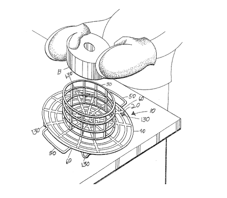
Fig. 1 is a perspective view of one embodiment of the
present invention:
Fig. 2 is a top plan view of a second embodiment thereof;
Fig. 3 is a schematic view showing the stacking means of
the first embodiment; and
Fig. 4 is a schematic view showing the stacking means of
the second embodiment.
Similar reference characters denote corresponding features
consistently throughout the attached drawings.
DETAILED DESCRIPTION OF THE PREFERRED EMBODIMENTB
The present invention comprises a wire cake rack 10 for
supporting either tubular, square, or rectangular cakes while
they cool. Referring to Fig. 1, the wire cake rack 10 includes
a round cake rack 20 for supporting tubular cakes, e.g. Bundt
cakes B. The round cake rack 20 is made with sides 30 in the
shape of an open top cylinder that are manufactured integrally
with a bottom 40 that
2a

JL
defines a greater diameter than the diameter of the sides 30. The
bottom 40 will be seen to include handles 50 on diametrically
opposite edges 60 of the bottom 40 as well as feet 130 attached to
four points of the underside of the bottom 40.
All of the above-described rack components will be understood
to be of wire construction with the rack 20 and sides presenting a
unanimous configuration allowing for adept support together with
sufficient cooling ability.
Referring now to Fig. 2, the wire cake rack 10 defines a
rectangular cake rack 70 for supporting rectangular cakes, e.g.
sheet or pound cakes. The rectangular cake rack 70 is made with
sides 80 in the shape of an open top rectangular box and is
manufactured integrally with a bottom 90 that is axially aligned
with the sides 80. The bottom 90 includes handles 100 on the two
edges 110 of the bottom 90 that are longer than the other two edges
120 of the bottom 90.
Referring now to Fig. 3, the round wire cake racks 20 can be
stacked together. The wire racks 20 are made of slightly different
diameters D so that they can stack inside of each other.
Similarly,.referring to Fig. 4, the rectangular wire racks 70 are
made of slightly different axial dimensions L and W so that they
can stack inside of each other.
It is to be understood that the present invention is not~
limited to the sole embodiments within the scope of the following.
claims.
3

Dessin représentatif
Une figure unique qui représente un dessin illustrant l'invention.
États administratifs

Pour une meilleure compréhension de l'état de la demande ou brevet qui figure sur cette page, la rubrique Mise en garde , et les descriptions de Brevet , États administratifs , Taxes périodiques et Historique des paiements devraient être consultées.

États administratifs

Titre Date
Date de délivrance prévu 2000-04-11
(22) Dépôt 1993-09-10
Requête d'examen 1994-01-05
(41) Mise à la disponibilité du public 1995-03-11
(45) Délivré 2000-04-11
Réputé périmé 2007-09-10

Historique d'abandonnement

Il n'y a pas d'historique d'abandonnement

Historique des paiements

Type de taxes Anniversaire Échéance Montant payé Date payée
Le dépôt d'une demande de brevet 0,00 $ 1993-09-10
Requête d'examen 200,00 $ 1994-01-05
Taxe de maintien en état - Demande - nouvelle loi 2 1995-09-11 50,00 $ 1995-08-21
Taxe de maintien en état - Demande - nouvelle loi 3 1996-09-10 50,00 $ 1996-08-16
Taxe de maintien en état - Demande - nouvelle loi 4 1997-09-10 50,00 $ 1997-08-27
Taxe de maintien en état - Demande - nouvelle loi 5 1998-09-10 75,00 $ 1998-04-08
Taxe de maintien en état - Demande - nouvelle loi 6 1999-09-10 75,00 $ 1999-09-01
Taxe finale 150,00 $ 2000-01-14
Taxe de maintien en état - brevet - nouvelle loi 7 2000-09-11 75,00 $ 2000-08-21
Taxe de maintien en état - brevet - nouvelle loi 8 2001-09-10 75,00 $ 2001-04-26
Taxe de maintien en état - brevet - nouvelle loi 9 2002-09-10 75,00 $ 2002-08-26
Taxe de maintien en état - brevet - nouvelle loi 10 2003-09-10 100,00 $ 2003-08-14
Taxe de maintien en état - brevet - nouvelle loi 11 2004-09-10 125,00 $ 2004-09-07
Taxe de maintien en état - brevet - nouvelle loi 12 2005-09-12 125,00 $ 2005-08-16
Titulaires au dossier

Les titulaires actuels et antérieures au dossier sont affichés en ordre alphabétique.

Titulaires actuels au dossier
LOCKETT, ELLA-WINN M.
Titulaires antérieures au dossier
S.O.
Les propriétaires antérieurs qui ne figurent pas dans la liste des « Propriétaires au dossier » apparaîtront dans d'autres documents au dossier.
Documents

Pour visionner les fichiers sélectionnés, entrer le code reCAPTCHA :


Pour visualiser une image, cliquer sur un lien dans la colonne description du document. Pour télécharger l'image (les images), cliquer l'une ou plusieurs cases à cocher dans la première colonne et ensuite cliquer sur le bouton "Télécharger sélection en format PDF (archive Zip)" ou le bouton "Télécharger sélection (en un fichier PDF fusionné)".

Liste des documents de brevet publiés et non publiés sur la BDBC .

Si vous avez des difficultés à accéder au contenu, veuillez communiquer avec le Centre de services à la clientèle au 1-866-997-1936, ou envoyer un courriel au Centre de service à la clientèle de l'OPIC.


Description du
Document 
Date
(yyyy-mm-dd) 
Nombre de pages   Taille de l'image (Ko) 
Dessins représentatifs 1998-05-12 1 39
Dessins représentatifs 2000-03-09 1 24
Description 1995-05-20 3 207
Page couverture 2000-03-09 1 54
Page couverture 1995-05-20 1 96
Abrégé 1995-05-20 1 68
Revendications 1995-05-20 2 97
Dessins 1995-05-20 3 165
Description 1998-04-22 4 238
Revendications 1998-04-22 2 64
Cession 1993-09-10 4 156
Poursuite-Amendment 1994-01-07 5 201
Poursuite-Amendment 1998-04-22 6 220
Taxes 1998-04-08 1 58
Poursuite-Amendment 1997-09-02 1 33
Poursuite-Amendment 1998-01-02 2 43
Taxes 2003-08-14 1 48
Taxes 2004-09-07 3 82
Correspondance 2000-01-14 1 58
Taxes 2000-08-21 1 56
Taxes 2001-04-26 1 54
Taxes 2002-08-26 1 58
Taxes 1997-08-27 1 57
Taxes 1999-09-01 1 56
Taxes 2005-08-16 1 23
Taxes 1996-08-16 1 55
Taxes 1995-08-21 1 49