Language selection

Search

Patent 2110607 Summary

Third-party information liability

Some of the information on this Web page has been provided by external sources. The Government of Canada is not responsible for the accuracy, reliability or currency of the information supplied by external sources. Users wishing to rely upon this information should consult directly with the source of the information. Content provided by external sources is not subject to official languages, privacy and accessibility requirements.

Claims and Abstract availability

Any discrepancies in the text and image of the Claims and Abstract are due to differing posting times. Text of the Claims and Abstract are posted:

  • At the time the application is open to public inspection;
  • At the time of issue of the patent (grant).
(12) Patent: (11) CA 2110607
(54) English Title: TOE WEB GLAND CUTTING TOOL
(54) French Title: OUTIL DE COUPE
Status: Expired
Bibliographic Data
(51) International Patent Classification (IPC):
  • A22B 3/08 (2006.01)
  • A22B 5/00 (2006.01)
  • A22C 11/12 (2006.01)
(72) Inventors :
  • BAERTLEIN, LEE A. (United States of America)
(73) Owners :
  • BAERTLEIN, LEE A. (United States of America)
(71) Applicants :
(74) Agent: SMART & BIGGAR
(74) Associate agent:
(45) Issued: 1999-01-26
(22) Filed Date: 1993-12-03
(41) Open to Public Inspection: 1994-09-24
Examination requested: 1995-11-14
Availability of licence: N/A
(25) Language of filing: English

Patent Cooperation Treaty (PCT): No

(30) Application Priority Data:
Application No. Country/Territory Date
08/035,420 United States of America 1993-03-23

Abstracts

English Abstract


A toe web gland cutter blade assembly having a
pair of plates mounted in a parallel spaced relation with
a cutting edge on the inside edge of each plate, a
cutting blade pivotally mounted between the plates, the
blade including a cutting edge on each side which
cooperates to cut the gland and a hook at the outer end
for drawing the gland into the space between the plates,
the hook including a cutting edge for cutting the gland
transversely to the cutting edges.


French Abstract

La présente invention vise un assemblage de tête mécanique à lames tranchantes constituée d'une paire de plaques montées en parallèle par rapport au tranchant de la rive intérieure de chaque plaque, d'une lame montée sur un pivot entre les plaques, la lame se terminant de chaque côté par des arêtes tranchantes qui travaillent de concert pour couper la bague, et d'un crochet à l'extrémité extérieure pour extraire la bague et la loger dans l'espace séparant les plaques, le crochet étant muni d'une arête tranchante pour couper la bague selon un axe transversal par rapport aux arêtes tranchantes.

Claims

Note: Claims are shown in the official language in which they were submitted.

-5-

THE EMBODIMENTS OF THE INVENTION IN WHICH AN EXCLUSIVE
PROPERTY OR PRIVILEGE IS CLAIMED ARE DEFINED AS FOLLOWS:

1. A toe web gland cutter blade assembly adaptable to a
universal power head, said assembly comprising a pair of
plates pivotally mounted in a parallel spaced relation on the
power head, each plate including a cutting edge along the
inside edge of one end of each of said plates, a cutter blade
mounted on the power head for pivotal motion between said
plates, a hook at the end of said cutter blade for drawing the
toe web gland into the cutting edge of said plates, said hook
includes a cutting edge which is transverse to the cutting
edges of said plates, said cutter blade and said plates
simultaneously in opposite directions whereby the cutting edge
of the cutter blade cooperates with the cutting edges of said
plates to cut the toe web gland.

2. The cutter blade assembly according to claim 1
wherein each of said plates and said blades includes a link
operatively connecting said plates and said blade to said
power head.

3. The cutter blade assembly according to claim 2
wherein said cutter blade and the plates are pivotally mounted
on a common axis.


-6-
4. A toe web gland cutting tool comprising a power
head, a pair of plates pivotally mounted on said power head, a
spacer mounted on one end of said plates for supporting said
plates in a parallel spaced relation, each plate having a
cutting edge on the inside of one end of each blade, a cutter
blade pivotally mounted on the power head in the space between
said plates, said blade including a hook at one end for
drawing the web gland between the plates; and including a
cutting edge on the end of said hook which is located
transverse to the cutting edges of said plates for cutting the
web gland, each of said plates and said blade including a link
for connecting said plates and said blade to said power head
for simultaneously pivoting said blade and said plates in
opposite directions whereby said blade passes through the
space between said plates.

5. The cutting tool according to claim 4 wherein said
plates and said blade are pivotally mounted on a common axis.

6. The cutting tool according to claim 5 wherein said
blade includes a hook at one end for drawing the web gland
between the blades.


-7-

7. The cutting tool according to claim 6 including a
cutting edge on the end of said hook for cutting the toe web
gland.

Description

Note: Descriptions are shown in the official language in which they were submitted.


r~

2 ~ 7
, . .

~; .
.

.
..
'
~ .
i, . .
. . .

~0~ WEB GLAND ~u lNG TOO~

: FIELD OF THE INVENTION
The present invention relates to cutter blades
for cutting and trimming animals for market and more
~ 5 particularly to a double cutting ~lade assembly for
Z~ removing the gland or web between the toes of the animal
which is also readily adaptable to a universal power
head.

-~ ~ BACKGROUND OF THE INVENTION
In the~preparation of livestock for market a
number of cutting and trimming stations are provided for
selectively removing various parts of the animal. Each
~ of the cutting steps requires a different type of utensil
" ~ in order to perform the required function. Most of these
~ 15~ tools arP adaptable to a universal power head such as
? ~ shown and~described in U.S. Patent No. 5,152,713,
~ entit~led "Universal Power Head For Hand Operated Tools."
Z' ;~ ~ A particularly troublesome trimming operation
~ is the removal of the gland or web between the toes of
','j~-A~ 20 swine. A certain amount of dexterity is required in
~ order to completely remove the gland. This involves at

~ 2~10(~i~37

. I .
least two cutting strokes which require additional time
to complete this step in the stripping process.

~- SUM~RY OF THE PRESENT INVENTION
The cutter blade assembly according to the
present invention includes a pair of plates which are
mounted in a parallel spaced relation with a cutting edge
provided on the inner edge of the walls of each of the
' platas. A planar blade is pivotally mounted in the space
,,
between the plates which includes a cutting edge on each
'~ 10 side of the blade and a hook on the outer end of the
,~ blade for pulling thP web or gland in the space between
,~ plates. The assembly is pivotally mounted on the
; universal head and simultaneously pivoted to completely
i~ remove the gland.
One of the primary advantages of the blade
a~sembly is the ability to perform this step in the
process in a single step.
A further advantage of the blade assembly is
the provision of a hook on the inner blade which draws
the gLand into the cutting edges of the plates thus
. '~ completely removing the gland in a single stroke.
Other principal features and advantages of the
invention will become ~pparent to those skilled in the
~ art upon review of the following drawings, the detailed
5 ~ 25 ~ descr1ption and the appended claims.

BRIEF DESCRIPTION OF THE DRAWINGS
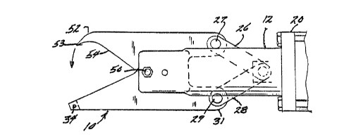
Figure l is a side elevation view of a
~- unlversal power head;
Figure 2 is a perspective view of the cutter
blade assembly;
Figure 3 is a view of the cutter assembly
~mounted in the universal head in the open position; and

~, ~

,~, :
!' ~

~" 2 1 1 ~ 7

-
~;i Figure 4 is a view o~ the cutter assembly shown
~' in the closed position~
Before explaining at least one embodiment o~
the invention in detail it is to be understood that the
invention is not limited in its application to the
details of construction and the arrangement of the
components set forth in the following description or
illustrat~d in the drawings. The invention is capable of
other embodiments or being practiced or carried out in
various ways. Also, it is to be understood that the
: phraseology and terminology employed herein is for the
~'~i purpose of description and should not be regarded as
, limiting.
:~
~' DETAILED VESCRIPTION OF THE PREFERRED EMBODIMENTS
The cutter assembly 10 according to the present
invention as shown in Figures 1 and 2 is shown mounted on
a universal power head 12. The power head generally
includes a housing or body 14 ha~ing a handle 16 on one
or more sides of the head. The cutter assembly 10 is
shown mounted on the housing 12 and actuated by means of
a pneumatic piston and cylinder assembly 20. Th2 piston
and cylinder assembly 20 is actuated by a trigger 22
provided on the handle--16. A trigger guard 23 is ~-
b '~ provided~in the front of each trigger 22. As is
generally understood actuation of the piston and cylinder
assembly 20 is accomplished by gripping the handle 16 and ~ -
, ~ squeezing the trigger 22. Actuation of the trigger 22 ~-~
pressurizes one end of the piston and cylinder assembly
20 to close the blade assembly 10 on the forward stroke
30~ of the piston 24. On release of the trigger 22 the other
end of the piston and cylinder assembly 20 is pressurized ~-
to open the blade assembly 10.
More particularly, and referring to Figures 2,
3 and 4 the cutter assembly 10 generally includes a pair


.9
: ' :
1~: ' ' '

: 1 2 ~ L O ~ ~) 7
.,:.
-4-
of cutter plates 30 interconnected at one end by a spacer
bar 32 and held in place by a pin 34. The plates 30 are
provided with a cutting edge 36, along the inside edge of
- one end of each of the plates 30 and a tab or extension
~ 5 31 at the other end. A cutter blade 40 is pivotally
!~ mounted between the plates 30 by means of a pin 50. The
; cutter blade 40 includes a hook 52 at the outer end
having a cutting edge 53 a~d a tab 42 at the other end.
A cutting edge 54 is provided along each side of the
cutter blade 40.
, It should be noted that the cutter assembly 10
is operatively connected to the piston 24 by links 26 and
28. The link 26 is connected to the tab 42 on the inner
end of blade 40 by a bolt 27. The links 28 are connected
~) 15 to tabs 31 on the end of plates 30 by bolts 29. Pivoting
!~'. of th~ cutter blade 40 between the plates 30 will move
,~ the hook 52 into the space between the cutting edges of
'~ ~he plates 30. The hook 52 will pull the gland between
the plates 30 so that the gland or web can be cut by the
closing motion of the ~utting edges 36 on the plates and
the cutting edge 53 on the hook 52.
~-~ Thus, it should be apparent that there has been
provided in accordance with the present invention a toe
web gland cutting tool--that fully satisfies the
objectives and advantages set forth above. Although the
invention has been described in conjunction with specific
embodiments thereof, it is evident that many
alternatives, modifications and variations will be
apparent to those skilled in the art. Accordingly, it is
intended to embrace all such alternatives, modif?ications
and variations that fall within the spirit and broad
SCOp2 of the appended claims.
' ! ':'
~T..'
' i '.~
' '.'' '-
~ ~,
,' ;~. i'
:~,'~.,.

Representative Drawing
A single figure which represents the drawing illustrating the invention.
Administrative Status

For a clearer understanding of the status of the application/patent presented on this page, the site Disclaimer , as well as the definitions for Patent , Administrative Status , Maintenance Fee  and Payment History  should be consulted.

Administrative Status

Title Date
Forecasted Issue Date 1999-01-26
(22) Filed 1993-12-03
(41) Open to Public Inspection 1994-09-24
Examination Requested 1995-11-14
(45) Issued 1999-01-26
Expired 2013-12-03

Abandonment History

There is no abandonment history.

Payment History

Fee Type Anniversary Year Due Date Amount Paid Paid Date
Application Fee $0.00 1993-12-03
Maintenance Fee - Application - New Act 2 1995-12-04 $50.00 1995-09-27
Maintenance Fee - Application - New Act 3 1996-12-03 $50.00 1996-09-30
Maintenance Fee - Application - New Act 4 1997-12-03 $50.00 1997-09-19
Maintenance Fee - Application - New Act 5 1998-12-03 $75.00 1998-09-24
Final Fee $150.00 1998-09-29
Maintenance Fee - Patent - New Act 6 1999-12-03 $150.00 1999-11-17
Maintenance Fee - Patent - New Act 7 2000-12-04 $75.00 2000-11-17
Maintenance Fee - Patent - New Act 8 2001-12-03 $75.00 2001-11-19
Maintenance Fee - Patent - New Act 9 2002-12-03 $75.00 2002-11-19
Maintenance Fee - Patent - New Act 10 2003-12-03 $200.00 2003-11-17
Maintenance Fee - Patent - New Act 11 2004-12-03 $250.00 2004-11-08
Back Payment of Fees $125.00 2005-11-08
Maintenance Fee - Patent - New Act 12 2005-12-05 $125.00 2005-11-08
Back Payment of Fees $125.00 2006-11-08
Maintenance Fee - Patent - New Act 13 2006-12-04 $125.00 2006-11-08
Maintenance Fee - Patent - New Act 14 2007-12-03 $250.00 2007-11-23
Maintenance Fee - Patent - New Act 15 2008-12-03 $450.00 2008-12-01
Maintenance Fee - Patent - New Act 16 2009-12-03 $450.00 2009-12-03
Maintenance Fee - Patent - New Act 17 2010-12-03 $450.00 2010-12-03
Maintenance Fee - Patent - New Act 18 2011-12-05 $450.00 2011-12-02
Maintenance Fee - Patent - New Act 19 2012-12-03 $650.00 2012-12-13
Owners on Record

Note: Records showing the ownership history in alphabetical order.

Current Owners on Record
BAERTLEIN, LEE A.
Past Owners on Record
None
Past Owners that do not appear in the "Owners on Record" listing will appear in other documentation within the application.
Documents

To view selected files, please enter reCAPTCHA code :


To view images, click a link in the Document Description column. To download the documents, select one or more checkboxes in the first column and then click the "Download Selected in PDF format (Zip Archive)" or the "Download Selected as Single PDF" button.

List of published and non-published patent-specific documents on the CPD .

If you have any difficulty accessing content, you can call the Client Service Centre at 1-866-997-1936 or send them an e-mail at CIPO Client Service Centre.


Document
Description 
Date
(yyyy-mm-dd) 
Number of pages   Size of Image (KB) 
Representative Drawing 1999-01-20 1 8
Cover Page 1995-04-08 1 73
Abstract 1995-04-08 1 87
Claims 1995-04-08 2 192
Drawings 1995-04-08 2 164
Description 1995-04-08 4 403
Claims 1998-04-29 3 71
Cover Page 1999-01-20 1 39
Correspondence 1998-09-29 2 54
Prosecution Correspondence 1998-04-09 1 42
Prosecution Correspondence 1995-11-14 1 40
Examiner Requisition 1997-10-10 1 33
Office Letter 1996-01-03 1 48
Fees 2009-12-03 1 28
Fees 2010-12-03 1 29
Fees 2011-12-02 1 24
Correspondence 2012-06-28 1 14
Fees 1996-09-30 1 66
Fees 1995-09-27 1 60