Sélection de la langue

Search

Sommaire du brevet 2110607 

Énoncé de désistement de responsabilité concernant l'information provenant de tiers

Une partie des informations de ce site Web a été fournie par des sources externes. Le gouvernement du Canada n'assume aucune responsabilité concernant la précision, l'actualité ou la fiabilité des informations fournies par les sources externes. Les utilisateurs qui désirent employer cette information devraient consulter directement la source des informations. Le contenu fourni par les sources externes n'est pas assujetti aux exigences sur les langues officielles, la protection des renseignements personnels et l'accessibilité.

Disponibilité de l'Abrégé et des Revendications

L'apparition de différences dans le texte et l'image des Revendications et de l'Abrégé dépend du moment auquel le document est publié. Les textes des Revendications et de l'Abrégé sont affichés :

  • lorsque la demande peut être examinée par le public;
  • lorsque le brevet est émis (délivrance).
(12) Brevet: (11) CA 2110607
(54) Titre français: OUTIL DE COUPE
(54) Titre anglais: TOE WEB GLAND CUTTING TOOL
Statut: Périmé
Données bibliographiques
(51) Classification internationale des brevets (CIB):
  • A22B 3/08 (2006.01)
  • A22B 5/00 (2006.01)
  • A22C 11/12 (2006.01)
(72) Inventeurs :
  • BAERTLEIN, LEE A. (Etats-Unis d'Amérique)
(73) Titulaires :
  • BAERTLEIN, LEE A. (Etats-Unis d'Amérique)
(71) Demandeurs :
(74) Agent: SMART & BIGGAR
(74) Co-agent:
(45) Délivré: 1999-01-26
(22) Date de dépôt: 1993-12-03
(41) Mise à la disponibilité du public: 1994-09-24
Requête d'examen: 1995-11-14
Licence disponible: S.O.
(25) Langue des documents déposés: Anglais

Traité de coopération en matière de brevets (PCT): Non

(30) Données de priorité de la demande:
Numéro de la demande Pays / territoire Date
08/035,420 Etats-Unis d'Amérique 1993-03-23

Abrégés

Abrégé français

La présente invention vise un assemblage de tête mécanique à lames tranchantes constituée d'une paire de plaques montées en parallèle par rapport au tranchant de la rive intérieure de chaque plaque, d'une lame montée sur un pivot entre les plaques, la lame se terminant de chaque côté par des arêtes tranchantes qui travaillent de concert pour couper la bague, et d'un crochet à l'extrémité extérieure pour extraire la bague et la loger dans l'espace séparant les plaques, le crochet étant muni d'une arête tranchante pour couper la bague selon un axe transversal par rapport aux arêtes tranchantes.


Abrégé anglais


A toe web gland cutter blade assembly having a
pair of plates mounted in a parallel spaced relation with
a cutting edge on the inside edge of each plate, a
cutting blade pivotally mounted between the plates, the
blade including a cutting edge on each side which
cooperates to cut the gland and a hook at the outer end
for drawing the gland into the space between the plates,
the hook including a cutting edge for cutting the gland
transversely to the cutting edges.

Revendications

Note : Les revendications sont présentées dans la langue officielle dans laquelle elles ont été soumises.


-5-

THE EMBODIMENTS OF THE INVENTION IN WHICH AN EXCLUSIVE
PROPERTY OR PRIVILEGE IS CLAIMED ARE DEFINED AS FOLLOWS:

1. A toe web gland cutter blade assembly adaptable to a
universal power head, said assembly comprising a pair of
plates pivotally mounted in a parallel spaced relation on the
power head, each plate including a cutting edge along the
inside edge of one end of each of said plates, a cutter blade
mounted on the power head for pivotal motion between said
plates, a hook at the end of said cutter blade for drawing the
toe web gland into the cutting edge of said plates, said hook
includes a cutting edge which is transverse to the cutting
edges of said plates, said cutter blade and said plates
simultaneously in opposite directions whereby the cutting edge
of the cutter blade cooperates with the cutting edges of said
plates to cut the toe web gland.

2. The cutter blade assembly according to claim 1
wherein each of said plates and said blades includes a link
operatively connecting said plates and said blade to said
power head.

3. The cutter blade assembly according to claim 2
wherein said cutter blade and the plates are pivotally mounted
on a common axis.


-6-
4. A toe web gland cutting tool comprising a power
head, a pair of plates pivotally mounted on said power head, a
spacer mounted on one end of said plates for supporting said
plates in a parallel spaced relation, each plate having a
cutting edge on the inside of one end of each blade, a cutter
blade pivotally mounted on the power head in the space between
said plates, said blade including a hook at one end for
drawing the web gland between the plates; and including a
cutting edge on the end of said hook which is located
transverse to the cutting edges of said plates for cutting the
web gland, each of said plates and said blade including a link
for connecting said plates and said blade to said power head
for simultaneously pivoting said blade and said plates in
opposite directions whereby said blade passes through the
space between said plates.

5. The cutting tool according to claim 4 wherein said
plates and said blade are pivotally mounted on a common axis.

6. The cutting tool according to claim 5 wherein said
blade includes a hook at one end for drawing the web gland
between the blades.


-7-

7. The cutting tool according to claim 6 including a
cutting edge on the end of said hook for cutting the toe web
gland.

Description

Note : Les descriptions sont présentées dans la langue officielle dans laquelle elles ont été soumises.

r~

2 ~ 7
, . .

~; .
.

.
..
'
~ .
i, . .
. . .

~0~ WEB GLAND ~u lNG TOO~

: FIELD OF THE INVENTION
The present invention relates to cutter blades
for cutting and trimming animals for market and more
~ 5 particularly to a double cutting ~lade assembly for
Z~ removing the gland or web between the toes of the animal
which is also readily adaptable to a universal power
head.

-~ ~ BACKGROUND OF THE INVENTION
In the~preparation of livestock for market a
number of cutting and trimming stations are provided for
selectively removing various parts of the animal. Each
~ of the cutting steps requires a different type of utensil
" ~ in order to perform the required function. Most of these
~ 15~ tools arP adaptable to a universal power head such as
? ~ shown and~described in U.S. Patent No. 5,152,713,
~ entit~led "Universal Power Head For Hand Operated Tools."
Z' ;~ ~ A particularly troublesome trimming operation
~ is the removal of the gland or web between the toes of
','j~-A~ 20 swine. A certain amount of dexterity is required in
~ order to completely remove the gland. This involves at

~ 2~10(~i~37

. I .
least two cutting strokes which require additional time
to complete this step in the stripping process.

~- SUM~RY OF THE PRESENT INVENTION
The cutter blade assembly according to the
present invention includes a pair of plates which are
mounted in a parallel spaced relation with a cutting edge
provided on the inner edge of the walls of each of the
' platas. A planar blade is pivotally mounted in the space
,,
between the plates which includes a cutting edge on each
'~ 10 side of the blade and a hook on the outer end of the
,~ blade for pulling thP web or gland in the space between
,~ plates. The assembly is pivotally mounted on the
; universal head and simultaneously pivoted to completely
i~ remove the gland.
One of the primary advantages of the blade
a~sembly is the ability to perform this step in the
process in a single step.
A further advantage of the blade assembly is
the provision of a hook on the inner blade which draws
the gLand into the cutting edges of the plates thus
. '~ completely removing the gland in a single stroke.
Other principal features and advantages of the
invention will become ~pparent to those skilled in the
~ art upon review of the following drawings, the detailed
5 ~ 25 ~ descr1ption and the appended claims.

BRIEF DESCRIPTION OF THE DRAWINGS
Figure l is a side elevation view of a
~- unlversal power head;
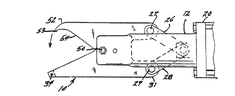
Figure 2 is a perspective view of the cutter
blade assembly;
Figure 3 is a view of the cutter assembly
~mounted in the universal head in the open position; and

~, ~

,~, :
!' ~

~" 2 1 1 ~ 7

-
~;i Figure 4 is a view o~ the cutter assembly shown
~' in the closed position~
Before explaining at least one embodiment o~
the invention in detail it is to be understood that the
invention is not limited in its application to the
details of construction and the arrangement of the
components set forth in the following description or
illustrat~d in the drawings. The invention is capable of
other embodiments or being practiced or carried out in
various ways. Also, it is to be understood that the
: phraseology and terminology employed herein is for the
~'~i purpose of description and should not be regarded as
, limiting.
:~
~' DETAILED VESCRIPTION OF THE PREFERRED EMBODIMENTS
The cutter assembly 10 according to the present
invention as shown in Figures 1 and 2 is shown mounted on
a universal power head 12. The power head generally
includes a housing or body 14 ha~ing a handle 16 on one
or more sides of the head. The cutter assembly 10 is
shown mounted on the housing 12 and actuated by means of
a pneumatic piston and cylinder assembly 20. Th2 piston
and cylinder assembly 20 is actuated by a trigger 22
provided on the handle--16. A trigger guard 23 is ~-
b '~ provided~in the front of each trigger 22. As is
generally understood actuation of the piston and cylinder
assembly 20 is accomplished by gripping the handle 16 and ~ -
, ~ squeezing the trigger 22. Actuation of the trigger 22 ~-~
pressurizes one end of the piston and cylinder assembly
20 to close the blade assembly 10 on the forward stroke
30~ of the piston 24. On release of the trigger 22 the other
end of the piston and cylinder assembly 20 is pressurized ~-
to open the blade assembly 10.
More particularly, and referring to Figures 2,
3 and 4 the cutter assembly 10 generally includes a pair


.9
: ' :
1~: ' ' '

: 1 2 ~ L O ~ ~) 7
.,:.
-4-
of cutter plates 30 interconnected at one end by a spacer
bar 32 and held in place by a pin 34. The plates 30 are
provided with a cutting edge 36, along the inside edge of
- one end of each of the plates 30 and a tab or extension
~ 5 31 at the other end. A cutter blade 40 is pivotally
!~ mounted between the plates 30 by means of a pin 50. The
; cutter blade 40 includes a hook 52 at the outer end
having a cutting edge 53 a~d a tab 42 at the other end.
A cutting edge 54 is provided along each side of the
cutter blade 40.
, It should be noted that the cutter assembly 10
is operatively connected to the piston 24 by links 26 and
28. The link 26 is connected to the tab 42 on the inner
end of blade 40 by a bolt 27. The links 28 are connected
~) 15 to tabs 31 on the end of plates 30 by bolts 29. Pivoting
!~'. of th~ cutter blade 40 between the plates 30 will move
,~ the hook 52 into the space between the cutting edges of
'~ ~he plates 30. The hook 52 will pull the gland between
the plates 30 so that the gland or web can be cut by the
closing motion of the ~utting edges 36 on the plates and
the cutting edge 53 on the hook 52.
~-~ Thus, it should be apparent that there has been
provided in accordance with the present invention a toe
web gland cutting tool--that fully satisfies the
objectives and advantages set forth above. Although the
invention has been described in conjunction with specific
embodiments thereof, it is evident that many
alternatives, modifications and variations will be
apparent to those skilled in the art. Accordingly, it is
intended to embrace all such alternatives, modif?ications
and variations that fall within the spirit and broad
SCOp2 of the appended claims.
' ! ':'
~T..'
' i '.~
' '.'' '-
~ ~,
,' ;~. i'
:~,'~.,.

Dessin représentatif
Une figure unique qui représente un dessin illustrant l'invention.
États administratifs

Pour une meilleure compréhension de l'état de la demande ou brevet qui figure sur cette page, la rubrique Mise en garde , et les descriptions de Brevet , États administratifs , Taxes périodiques et Historique des paiements devraient être consultées.

États administratifs

Titre Date
Date de délivrance prévu 1999-01-26
(22) Dépôt 1993-12-03
(41) Mise à la disponibilité du public 1994-09-24
Requête d'examen 1995-11-14
(45) Délivré 1999-01-26
Expiré 2013-12-03

Historique d'abandonnement

Il n'y a pas d'historique d'abandonnement

Historique des paiements

Type de taxes Anniversaire Échéance Montant payé Date payée
Le dépôt d'une demande de brevet 0,00 $ 1993-12-03
Taxe de maintien en état - Demande - nouvelle loi 2 1995-12-04 50,00 $ 1995-09-27
Taxe de maintien en état - Demande - nouvelle loi 3 1996-12-03 50,00 $ 1996-09-30
Taxe de maintien en état - Demande - nouvelle loi 4 1997-12-03 50,00 $ 1997-09-19
Taxe de maintien en état - Demande - nouvelle loi 5 1998-12-03 75,00 $ 1998-09-24
Taxe finale 150,00 $ 1998-09-29
Taxe de maintien en état - brevet - nouvelle loi 6 1999-12-03 150,00 $ 1999-11-17
Taxe de maintien en état - brevet - nouvelle loi 7 2000-12-04 75,00 $ 2000-11-17
Taxe de maintien en état - brevet - nouvelle loi 8 2001-12-03 75,00 $ 2001-11-19
Taxe de maintien en état - brevet - nouvelle loi 9 2002-12-03 75,00 $ 2002-11-19
Taxe de maintien en état - brevet - nouvelle loi 10 2003-12-03 200,00 $ 2003-11-17
Taxe de maintien en état - brevet - nouvelle loi 11 2004-12-03 250,00 $ 2004-11-08
Paiement des arriérés de taxes 125,00 $ 2005-11-08
Taxe de maintien en état - brevet - nouvelle loi 12 2005-12-05 125,00 $ 2005-11-08
Paiement des arriérés de taxes 125,00 $ 2006-11-08
Taxe de maintien en état - brevet - nouvelle loi 13 2006-12-04 125,00 $ 2006-11-08
Taxe de maintien en état - brevet - nouvelle loi 14 2007-12-03 250,00 $ 2007-11-23
Taxe de maintien en état - brevet - nouvelle loi 15 2008-12-03 450,00 $ 2008-12-01
Taxe de maintien en état - brevet - nouvelle loi 16 2009-12-03 450,00 $ 2009-12-03
Taxe de maintien en état - brevet - nouvelle loi 17 2010-12-03 450,00 $ 2010-12-03
Taxe de maintien en état - brevet - nouvelle loi 18 2011-12-05 450,00 $ 2011-12-02
Taxe de maintien en état - brevet - nouvelle loi 19 2012-12-03 650,00 $ 2012-12-13
Titulaires au dossier

Les titulaires actuels et antérieures au dossier sont affichés en ordre alphabétique.

Titulaires actuels au dossier
BAERTLEIN, LEE A.
Titulaires antérieures au dossier
S.O.
Les propriétaires antérieurs qui ne figurent pas dans la liste des « Propriétaires au dossier » apparaîtront dans d'autres documents au dossier.
Documents

Pour visionner les fichiers sélectionnés, entrer le code reCAPTCHA :


Pour visualiser une image, cliquer sur un lien dans la colonne description du document. Pour télécharger l'image (les images), cliquer l'une ou plusieurs cases à cocher dans la première colonne et ensuite cliquer sur le bouton "Télécharger sélection en format PDF (archive Zip)" ou le bouton "Télécharger sélection (en un fichier PDF fusionné)".

Liste des documents de brevet publiés et non publiés sur la BDBC .

Si vous avez des difficultés à accéder au contenu, veuillez communiquer avec le Centre de services à la clientèle au 1-866-997-1936, ou envoyer un courriel au Centre de service à la clientèle de l'OPIC.


Description du
Document 
Date
(yyyy-mm-dd) 
Nombre de pages   Taille de l'image (Ko) 
Dessins représentatifs 1999-01-20 1 8
Page couverture 1995-04-08 1 73
Abrégé 1995-04-08 1 87
Revendications 1995-04-08 2 192
Dessins 1995-04-08 2 164
Description 1995-04-08 4 403
Revendications 1998-04-29 3 71
Page couverture 1999-01-20 1 39
Correspondance 1998-09-29 2 54
Correspondance de la poursuite 1998-04-09 1 42
Correspondance de la poursuite 1995-11-14 1 40
Demande d'examen 1997-10-10 1 33
Lettre du bureau 1996-01-03 1 48
Taxes 2009-12-03 1 28
Taxes 2010-12-03 1 29
Taxes 2011-12-02 1 24
Correspondance 2012-06-28 1 14
Taxes 1996-09-30 1 66
Taxes 1995-09-27 1 60