Language selection

Search

Patent 2116203 Summary

Third-party information liability

Some of the information on this Web page has been provided by external sources. The Government of Canada is not responsible for the accuracy, reliability or currency of the information supplied by external sources. Users wishing to rely upon this information should consult directly with the source of the information. Content provided by external sources is not subject to official languages, privacy and accessibility requirements.

Claims and Abstract availability

Any discrepancies in the text and image of the Claims and Abstract are due to differing posting times. Text of the Claims and Abstract are posted:

  • At the time the application is open to public inspection;
  • At the time of issue of the patent (grant).
(12) Patent: (11) CA 2116203
(54) English Title: A PULL-OUT GUIDE FOR DRAWERS
(54) French Title: GLISSIERE DE TIROIR ESCAMOTABLE
Status: Deemed expired
Bibliographic Data
(51) International Patent Classification (IPC):
  • A47B 88/14 (2006.01)
  • A47B 88/04 (2006.01)
(72) Inventors :
  • ROCK, ERICH (Austria)
  • DUBACH, FREDI (Switzerland)
(73) Owners :
  • JULIUS BLUM GESELLSCHAFT M.B.H. (Not Available)
(71) Applicants :
(74) Agent: MARKS & CLERK
(74) Associate agent:
(45) Issued: 2001-01-30
(22) Filed Date: 1994-02-22
(41) Open to Public Inspection: 1994-09-05
Examination requested: 1995-02-09
Availability of licence: N/A
(25) Language of filing: English

Patent Cooperation Treaty (PCT): No

(30) Application Priority Data:
Application No. Country/Territory Date
A 412/93 Austria 1993-03-04

Abstracts

English Abstract


A pull-out guide for drawers, having a support rail on the
carcass side and a pull-out rail on the loading side on
each side of the drawer, rollers which transmit the load
being mounted on the rails. The rollers of the support
rails and of the pull-out rails are offset perpendicular to
the direction of pulling out the pull-out rails such that
the pull-out rails are guided on two tracks. The pull-out
rails each have at least one horizontal tab which projects
below the running web of the support rail and forms a lift
protection means for the drawer.


Claims

Note: Claims are shown in the official language in which they were submitted.


THE EMBODIMENTS OF THE INVENTION IN WHICH AN EXCLUSIVE
PROPERTY OR PRIVILEGE IS CLAIMED ARE DEFINED AS FOLLOWS:

1. A pull-out guide fitting to be mounted on a side
of a drawer to guide sliding movement of the drawer into
and out of a furniture body, said fitting comprising:

a longitudinal support rail to be mounted on a side of
the furniture body;

a longitudinal pull-out rail to be mounted on a side
of said drawer;

said support rail and said pull-out rail having
respective longitudinal running webs

said support rail having mounted thereon at least one
guide member running on said running web of said pull-out
rail during relative longitudinal movement between said
rails:

said pull-out rail having mounted thereon at least one
guide member running on said running web of said support
rail during said relative longitudinal movement;

said at least one guide member of said pull-out rail
and said at least one guide member of said support rail
being offset in a direction transverse to a direction of
said relative longitudinal movement, such that movement of
said pull-out rail is guided along two tracks spaced in
said transverse direction; and

said pull-out rail having extended therefrom at least
one horizontal tab projecting below said running web of
said support rail, thereby preventing said pull-out rail
from being lifted off said support rail.


2. The fitting as claimed in claim 1, wherein said
pull-out rail has plural, longitudinally spaced horizontal
tabs.

3. The fitting as claimed in claim 2, wherein said
pull-out rail has three horizontal tabs.

4. The fitting as claimed in claim 2, further
comprising an eccentric mounted for rotation about a
vertical axis on a frontmost tab of said tabs at a position
to abut a front end of said support rail at a pushed in
position of said pull-out rail relative to said support
rail.

5. The fitting as claimed in claim 1, wherein said
guide members comprise rollers.

6. The fitting as claimed in claim 1, wherein said
guide member of said support rail comprises a roller
mounted on a side of said support rail opposite said
running web thereof.

7. The fitting as claimed in claim 1, wherein said
guide member of said support rail is mounted on a side
thereof opposite said running web thereof.


Description

Note: Descriptions are shown in the official language in which they were submitted.


CA 02116203 1998-11-02
A PULL-OUT GUIDE FOR DRAWERS
The invention relates to a pull-out guide for drawers and
more particularly, the invention relates to a pull-out
guide for drawers, having a support rail on the carcass
side and a pull-out rail on the loading side on each side
of the drawer. Rollers or slide means which transmit the
load being mounted on the rails and the rails having
running webs for the rollers or slide means and the rollers
or slide means of the support rails and of the pull-out
rails are offset perpendicular to the direction of pulling
out the pull-out rails such that the pull-out rails are
guided on two tracks.
One object of the invention is to improve a pull-out guide
of the above-mentioned type in such a way that it has a
lift protection means which prevents the drawer from being
lifted undesirably away from the support rails on the
carcass side, while removal of the drawer from the
2o furniture carcass is not prevented: even in cases when
there is little free space available between the drawers of
a furniture carcass which are arranged one above the other.
The object of the invention is achieved by making use of
the pull-out rails each having at least one horizontal tab
which projects below the running web of the support rail
and forms a lift protection means for the drawer.
A particularly stable construction is provided if each
3o pull-out rail has three horizontal tabs.
i


CA 02116203 1998-11-02
In accordance with one aspect of the present invention,
there is provided a pull-out guide fitting to be mounted on
a side of a drawer to guide sliding movement of the drawer
into and out of a furniture body, the fitting comprising:
a longitudinal support rail to be mounted on a side of
the furniture body
a longitudinal pull-out rail to be mounted on a side
of the drawer
the support rail and the pull-out rail having
to respective longitudinal running webs
the support rail having mounted thereon at least one
guide member running on the running web of the pull-out
rail during relative longitudinal movement between the
rails
the pull-out rail having mounted thereon at least one
guide member running on the running web of the support rail
during the relative longitudinal movement
the at least one guide member of the pull-out rail and
the at least one guide member of the support rail being
20 offset in a direction transverse to a direction of the
relative longitudinal movement, such that movement of the
pull-out rail is guided along two tracks spaced in the
transverse direction; and
the pull-out rail having extended therefrom at least
one horizontal tab projecting below the running web of the
support rail, thereby preventing the pull-out rail from
being lifted off the support rail.
2


CA 02116203 1998-11-02
Having thus described the invention, reference will now be
made to the accompanying drawings illustrating preferred
embodiments and in which:
Fig. 1 is an end view of a frame of the drawer and one side
of the pull-out guide fitting;
Fig. 2 is a side view of the drawer and of the pull-out
guide fitting, with the drawer closed:
Fig. 3 is a side view of a drawer and of a pull-out guide
fitting, with the drawer pulled outs
1o Fig. 4 is a horizontal section through a frame and a pull
out guide fitting on one side of the drawer, with the
drawer closed;
Fig. 5 is a side view of the pull-out rail, partially in
section;
Fig. 6 is a horizontal section through a pull-out rail; and
Fig. 7 is a section through a pull-out rail.
Similar numerals in the figures denote similar elements.
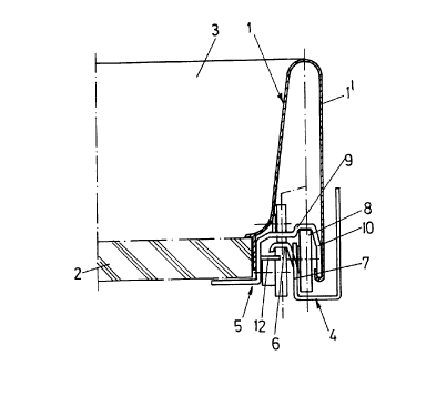
2o Of the drawer, only the drawer frame 1, the drawer base 2
and the drawer rear wall 3 are shown. For the sake of
clarity, the front panel has been omitted.
On each side of the drawer, the pull-out guide is covered
by the drawer frame 1. It is formed by a support rail 4,
which is secured to a carcass side wall, and a pull-out
rail 5, which is secured to the drawer side wall or to the
drawer base 2.
3


CA 02116203 1998-11-02
The support rail 4 has a horizontal running web 6 directed
towards the drawer and constructed at the upper edge of a
vertical web 7. The vertical web 7 carries, at the front
end of the support rail 4, a roller 8 which is secured to
the side of the vertical web opposite the running web 6.
This means that the roller 8 is located between the
vertical web 7 and the carcass side wall or the outer wall
1' of the double-walled drawer frame 1.
1o The pull-out rail 5 reaches over the running web 6 and the
vertical web 7 and the roller 8 of the support rail 4. Its
running web 9 thus lies on the outside of the running web 6
of the support rail 4. Furthermore, the pull-out rail 5
has an outer free marginal web 10 in which the drawer frame
1 is suspended by means of its outer wall 1'.
At the rear end, each pull-out rail 5 is provided with two
rollers 11 which are arranged one above the other and run
along against the running web 6 of the support rail 4,
2o respectively from above or from below.
As can be seen from Figs. 1 to 3, each pull-out rail 5 is
provided with three horizontal tabs 12 which, from the
side, project below the running web 6 of the support rail
4. These tabs 12 form a lift protection means which
prevents the pull-out rail 5, and thus the entire drawer,
from being undesirably lifted away from the support rails
4.
4


CA 02116203 1998-11-02
Because the tabs 12 are located together with the rollers
11 on the inner track of the pull-out guide fitting, when
the drawer is taken completely out of the carcass they do
not have to be raised over the rollers 8 of the support
rails 4. The pull-out rails 6 can thus be pulled straight
out of the furniture carcass. To take the drawer right out
of the carcass, the drawer only needs to be raised far
enough for the stops 13, 14 to be guided over the rollers
8.
In the frontmost tab 12 of each pull-out rail 5 there is
mounted an eccentric 15 which is rotatable about a vertical
axis. As can be seen in particular from Figs. 5 and 6,
when the drawer is pushed in the eccentric 15 abuts against
the associated support rail 4. By adjusting the eccentric
15, the effect is that on pushing in the drawer the front
panel does not strike against the furniture carcass. The
spacing between the front panel and the furniture carcass
or the side walls thereof is adjusted by turning the
2o eccentric 15. Because the energy of moving the drawer is
taken up between the rails 4, 5, the holding of the front
panel on the drawer frames 1 is prevented from working
loose.
Although embodiments of the invention have been described
above, it is not limited thereto and it will be apparent to
those skilled in the art that numerous modifications form
part of the present invention insofar as they do not depart
from the spirit, nature and scope of the claimed and
so described invention.
5

Representative Drawing
A single figure which represents the drawing illustrating the invention.
Administrative Status

For a clearer understanding of the status of the application/patent presented on this page, the site Disclaimer , as well as the definitions for Patent , Administrative Status , Maintenance Fee  and Payment History  should be consulted.

Administrative Status

Title Date
Forecasted Issue Date 2001-01-30
(22) Filed 1994-02-22
(41) Open to Public Inspection 1994-09-05
Examination Requested 1995-02-09
(45) Issued 2001-01-30
Deemed Expired 2003-02-24

Abandonment History

There is no abandonment history.

Payment History

Fee Type Anniversary Year Due Date Amount Paid Paid Date
Application Fee $0.00 1994-02-22
Registration of a document - section 124 $0.00 1994-08-05
Request for Examination $400.00 1995-02-09
Maintenance Fee - Application - New Act 2 1996-02-22 $100.00 1996-01-24
Maintenance Fee - Application - New Act 3 1997-02-24 $100.00 1997-01-29
Maintenance Fee - Application - New Act 4 1998-02-23 $100.00 1998-02-09
Maintenance Fee - Application - New Act 5 1999-02-22 $150.00 1999-02-09
Maintenance Fee - Application - New Act 6 2000-02-22 $150.00 2000-01-28
Final Fee $300.00 2000-10-23
Maintenance Fee - Patent - New Act 7 2001-02-22 $150.00 2001-01-31
Owners on Record

Note: Records showing the ownership history in alphabetical order.

Current Owners on Record
JULIUS BLUM GESELLSCHAFT M.B.H.
Past Owners on Record
DUBACH, FREDI
ROCK, ERICH
Past Owners that do not appear in the "Owners on Record" listing will appear in other documentation within the application.
Documents

To view selected files, please enter reCAPTCHA code :


To view images, click a link in the Document Description column. To download the documents, select one or more checkboxes in the first column and then click the "Download Selected in PDF format (Zip Archive)" or the "Download Selected as Single PDF" button.

List of published and non-published patent-specific documents on the CPD .

If you have any difficulty accessing content, you can call the Client Service Centre at 1-866-997-1936 or send them an e-mail at CIPO Client Service Centre.


Document
Description 
Date
(yyyy-mm-dd) 
Number of pages   Size of Image (KB) 
Abstract 1998-11-02 1 17
Description 1998-11-02 5 184
Claims 1998-11-02 2 64
Cover Page 2001-01-05 1 29
Drawings 1995-06-10 5 104
Cover Page 1995-06-10 1 37
Claims 1995-06-10 1 41
Abstract 1995-06-10 1 32
Description 1995-06-10 3 193
Representative Drawing 2001-01-05 1 7
Representative Drawing 1998-08-12 1 10
Prosecution-Amendment 1998-07-17 3 4
Assignment 1994-02-22 5 421
Prosecution-Amendment 1995-02-09 2 77
Correspondence 2000-10-23 1 33
Prosecution-Amendment 1997-07-03 1 24
Prosecution-Amendment 1998-11-02 11 359
Fees 1997-01-29 1 60
Fees 1996-01-24 1 60