Sélection de la langue

Search

Sommaire du brevet 2116203 

Énoncé de désistement de responsabilité concernant l'information provenant de tiers

Une partie des informations de ce site Web a été fournie par des sources externes. Le gouvernement du Canada n'assume aucune responsabilité concernant la précision, l'actualité ou la fiabilité des informations fournies par les sources externes. Les utilisateurs qui désirent employer cette information devraient consulter directement la source des informations. Le contenu fourni par les sources externes n'est pas assujetti aux exigences sur les langues officielles, la protection des renseignements personnels et l'accessibilité.

Disponibilité de l'Abrégé et des Revendications

L'apparition de différences dans le texte et l'image des Revendications et de l'Abrégé dépend du moment auquel le document est publié. Les textes des Revendications et de l'Abrégé sont affichés :

  • lorsque la demande peut être examinée par le public;
  • lorsque le brevet est émis (délivrance).
(12) Brevet: (11) CA 2116203
(54) Titre français: GLISSIERE DE TIROIR ESCAMOTABLE
(54) Titre anglais: A PULL-OUT GUIDE FOR DRAWERS
Statut: Périmé et au-delà du délai pour l’annulation
Données bibliographiques
(51) Classification internationale des brevets (CIB):
(72) Inventeurs :
  • ROCK, ERICH (Autriche)
  • DUBACH, FREDI (Suisse)
(73) Titulaires :
  • JULIUS BLUM GESELLSCHAFT M.B.H.
(71) Demandeurs :
  • JULIUS BLUM GESELLSCHAFT M.B.H. (Autriche)
(74) Agent: MARKS & CLERK
(74) Co-agent:
(45) Délivré: 2001-01-30
(22) Date de dépôt: 1994-02-22
(41) Mise à la disponibilité du public: 1994-09-05
Requête d'examen: 1995-02-09
Licence disponible: S.O.
Cédé au domaine public: S.O.
(25) Langue des documents déposés: Anglais

Traité de coopération en matière de brevets (PCT): Non

(30) Données de priorité de la demande:
Numéro de la demande Pays / territoire Date
A 412/93 (Autriche) 1993-03-04

Abrégés

Abrégé anglais


A pull-out guide for drawers, having a support rail on the
carcass side and a pull-out rail on the loading side on
each side of the drawer, rollers which transmit the load
being mounted on the rails. The rollers of the support
rails and of the pull-out rails are offset perpendicular to
the direction of pulling out the pull-out rails such that
the pull-out rails are guided on two tracks. The pull-out
rails each have at least one horizontal tab which projects
below the running web of the support rail and forms a lift
protection means for the drawer.

Revendications

Note : Les revendications sont présentées dans la langue officielle dans laquelle elles ont été soumises.


THE EMBODIMENTS OF THE INVENTION IN WHICH AN EXCLUSIVE
PROPERTY OR PRIVILEGE IS CLAIMED ARE DEFINED AS FOLLOWS:
1. A pull-out guide fitting to be mounted on a side
of a drawer to guide sliding movement of the drawer into
and out of a furniture body, said fitting comprising:
a longitudinal support rail to be mounted on a side of
the furniture body;
a longitudinal pull-out rail to be mounted on a side
of said drawer;
said support rail and said pull-out rail having
respective longitudinal running webs
said support rail having mounted thereon at least one
guide member running on said running web of said pull-out
rail during relative longitudinal movement between said
rails:
said pull-out rail having mounted thereon at least one
guide member running on said running web of said support
rail during said relative longitudinal movement;
said at least one guide member of said pull-out rail
and said at least one guide member of said support rail
being offset in a direction transverse to a direction of
said relative longitudinal movement, such that movement of
said pull-out rail is guided along two tracks spaced in
said transverse direction; and
said pull-out rail having extended therefrom at least
one horizontal tab projecting below said running web of
said support rail, thereby preventing said pull-out rail
from being lifted off said support rail.

2. The fitting as claimed in claim 1, wherein said
pull-out rail has plural, longitudinally spaced horizontal
tabs.
3. The fitting as claimed in claim 2, wherein said
pull-out rail has three horizontal tabs.
4. The fitting as claimed in claim 2, further
comprising an eccentric mounted for rotation about a
vertical axis on a frontmost tab of said tabs at a position
to abut a front end of said support rail at a pushed in
position of said pull-out rail relative to said support
rail.
5. The fitting as claimed in claim 1, wherein said
guide members comprise rollers.
6. The fitting as claimed in claim 1, wherein said
guide member of said support rail comprises a roller
mounted on a side of said support rail opposite said
running web thereof.
7. The fitting as claimed in claim 1, wherein said
guide member of said support rail is mounted on a side
thereof opposite said running web thereof.

Description

Note : Les descriptions sont présentées dans la langue officielle dans laquelle elles ont été soumises.

CA 02116203 1998-11-02
A PULL-OUT GUIDE FOR DRAWERS
The invention relates to a pull-out guide for drawers and
more particularly, the invention relates to a pull-out
guide for drawers, having a support rail on the carcass
side and a pull-out rail on the loading side on each side
of the drawer. Rollers or slide means which transmit the
load being mounted on the rails and the rails having
running webs for the rollers or slide means and the rollers
or slide means of the support rails and of the pull-out
rails are offset perpendicular to the direction of pulling
out the pull-out rails such that the pull-out rails are
guided on two tracks.
One object of the invention is to improve a pull-out guide
of the above-mentioned type in such a way that it has a
lift protection means which prevents the drawer from being
lifted undesirably away from the support rails on the
carcass side, while removal of the drawer from the
2o furniture carcass is not prevented: even in cases when
there is little free space available between the drawers of
a furniture carcass which are arranged one above the other.
The object of the invention is achieved by making use of
the pull-out rails each having at least one horizontal tab
which projects below the running web of the support rail
and forms a lift protection means for the drawer.
A particularly stable construction is provided if each
3o pull-out rail has three horizontal tabs.
i

CA 02116203 1998-11-02
In accordance with one aspect of the present invention,
there is provided a pull-out guide fitting to be mounted on
a side of a drawer to guide sliding movement of the drawer
into and out of a furniture body, the fitting comprising:
a longitudinal support rail to be mounted on a side of
the furniture body
a longitudinal pull-out rail to be mounted on a side
of the drawer
the support rail and the pull-out rail having
to respective longitudinal running webs
the support rail having mounted thereon at least one
guide member running on the running web of the pull-out
rail during relative longitudinal movement between the
rails
the pull-out rail having mounted thereon at least one
guide member running on the running web of the support rail
during the relative longitudinal movement
the at least one guide member of the pull-out rail and
the at least one guide member of the support rail being
20 offset in a direction transverse to a direction of the
relative longitudinal movement, such that movement of the
pull-out rail is guided along two tracks spaced in the
transverse direction; and
the pull-out rail having extended therefrom at least
one horizontal tab projecting below the running web of the
support rail, thereby preventing the pull-out rail from
being lifted off the support rail.
2

CA 02116203 1998-11-02
Having thus described the invention, reference will now be
made to the accompanying drawings illustrating preferred
embodiments and in which:
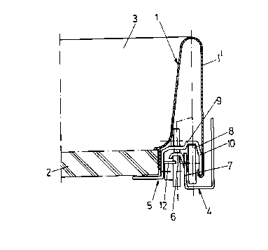
Fig. 1 is an end view of a frame of the drawer and one side
of the pull-out guide fitting;
Fig. 2 is a side view of the drawer and of the pull-out
guide fitting, with the drawer closed:
Fig. 3 is a side view of a drawer and of a pull-out guide
fitting, with the drawer pulled outs
1o Fig. 4 is a horizontal section through a frame and a pull
out guide fitting on one side of the drawer, with the
drawer closed;
Fig. 5 is a side view of the pull-out rail, partially in
section;
Fig. 6 is a horizontal section through a pull-out rail; and
Fig. 7 is a section through a pull-out rail.
Similar numerals in the figures denote similar elements.
2o Of the drawer, only the drawer frame 1, the drawer base 2
and the drawer rear wall 3 are shown. For the sake of
clarity, the front panel has been omitted.
On each side of the drawer, the pull-out guide is covered
by the drawer frame 1. It is formed by a support rail 4,
which is secured to a carcass side wall, and a pull-out
rail 5, which is secured to the drawer side wall or to the
drawer base 2.
3

CA 02116203 1998-11-02
The support rail 4 has a horizontal running web 6 directed
towards the drawer and constructed at the upper edge of a
vertical web 7. The vertical web 7 carries, at the front
end of the support rail 4, a roller 8 which is secured to
the side of the vertical web opposite the running web 6.
This means that the roller 8 is located between the
vertical web 7 and the carcass side wall or the outer wall
1' of the double-walled drawer frame 1.
1o The pull-out rail 5 reaches over the running web 6 and the
vertical web 7 and the roller 8 of the support rail 4. Its
running web 9 thus lies on the outside of the running web 6
of the support rail 4. Furthermore, the pull-out rail 5
has an outer free marginal web 10 in which the drawer frame
1 is suspended by means of its outer wall 1'.
At the rear end, each pull-out rail 5 is provided with two
rollers 11 which are arranged one above the other and run
along against the running web 6 of the support rail 4,
2o respectively from above or from below.
As can be seen from Figs. 1 to 3, each pull-out rail 5 is
provided with three horizontal tabs 12 which, from the
side, project below the running web 6 of the support rail
4. These tabs 12 form a lift protection means which
prevents the pull-out rail 5, and thus the entire drawer,
from being undesirably lifted away from the support rails
4.
4

CA 02116203 1998-11-02
Because the tabs 12 are located together with the rollers
11 on the inner track of the pull-out guide fitting, when
the drawer is taken completely out of the carcass they do
not have to be raised over the rollers 8 of the support
rails 4. The pull-out rails 6 can thus be pulled straight
out of the furniture carcass. To take the drawer right out
of the carcass, the drawer only needs to be raised far
enough for the stops 13, 14 to be guided over the rollers
8.
In the frontmost tab 12 of each pull-out rail 5 there is
mounted an eccentric 15 which is rotatable about a vertical
axis. As can be seen in particular from Figs. 5 and 6,
when the drawer is pushed in the eccentric 15 abuts against
the associated support rail 4. By adjusting the eccentric
15, the effect is that on pushing in the drawer the front
panel does not strike against the furniture carcass. The
spacing between the front panel and the furniture carcass
or the side walls thereof is adjusted by turning the
2o eccentric 15. Because the energy of moving the drawer is
taken up between the rails 4, 5, the holding of the front
panel on the drawer frames 1 is prevented from working
loose.
Although embodiments of the invention have been described
above, it is not limited thereto and it will be apparent to
those skilled in the art that numerous modifications form
part of the present invention insofar as they do not depart
from the spirit, nature and scope of the claimed and
so described invention.
5

Dessin représentatif
Une figure unique qui représente un dessin illustrant l'invention.
États administratifs

2024-08-01 : Dans le cadre de la transition vers les Brevets de nouvelle génération (BNG), la base de données sur les brevets canadiens (BDBC) contient désormais un Historique d'événement plus détaillé, qui reproduit le Journal des événements de notre nouvelle solution interne.

Veuillez noter que les événements débutant par « Inactive : » se réfèrent à des événements qui ne sont plus utilisés dans notre nouvelle solution interne.

Pour une meilleure compréhension de l'état de la demande ou brevet qui figure sur cette page, la rubrique Mise en garde , et les descriptions de Brevet , Historique d'événement , Taxes périodiques et Historique des paiements devraient être consultées.

Historique d'événement

Description Date
Inactive : CIB expirée 2017-01-01
Inactive : CIB de MCD 2006-03-11
Le délai pour l'annulation est expiré 2003-02-24
Lettre envoyée 2002-02-22
Accordé par délivrance 2001-01-30
Inactive : Page couverture publiée 2001-01-29
Inactive : Taxe finale reçue 2000-10-23
Préoctroi 2000-10-23
Lettre envoyée 2000-08-02
Un avis d'acceptation est envoyé 2000-08-02
Inactive : Approuvée aux fins d'acceptation (AFA) 2000-07-18
Modification reçue - modification volontaire 1998-11-02
Inactive : Dem. de l'examinateur par.30(2) Règles 1998-07-17
Inactive : Dem. traitée sur TS dès date d'ent. journal 1998-02-06
Inactive : Renseign. sur l'état - Complets dès date d'ent. journ. 1998-02-06
Toutes les exigences pour l'examen - jugée conforme 1995-02-09
Exigences pour une requête d'examen - jugée conforme 1995-02-09
Demande publiée (accessible au public) 1994-09-05

Historique d'abandonnement

Il n'y a pas d'historique d'abandonnement

Taxes périodiques

Le dernier paiement a été reçu le 2000-01-28

Avis : Si le paiement en totalité n'a pas été reçu au plus tard à la date indiquée, une taxe supplémentaire peut être imposée, soit une des taxes suivantes :

  • taxe de rétablissement ;
  • taxe pour paiement en souffrance ; ou
  • taxe additionnelle pour le renversement d'une péremption réputée.

Les taxes sur les brevets sont ajustées au 1er janvier de chaque année. Les montants ci-dessus sont les montants actuels s'ils sont reçus au plus tard le 31 décembre de l'année en cours.
Veuillez vous référer à la page web des taxes sur les brevets de l'OPIC pour voir tous les montants actuels des taxes.

Historique des taxes

Type de taxes Anniversaire Échéance Date payée
Requête d'examen - générale 1995-02-09
TM (demande, 4e anniv.) - générale 04 1998-02-23 1998-02-09
TM (demande, 5e anniv.) - générale 05 1999-02-22 1999-02-09
TM (demande, 6e anniv.) - générale 06 2000-02-22 2000-01-28
Taxe finale - générale 2000-10-23
TM (brevet, 7e anniv.) - générale 2001-02-22 2001-01-31
Titulaires au dossier

Les titulaires actuels et antérieures au dossier sont affichés en ordre alphabétique.

Titulaires actuels au dossier
JULIUS BLUM GESELLSCHAFT M.B.H.
Titulaires antérieures au dossier
ERICH ROCK
FREDI DUBACH
Les propriétaires antérieurs qui ne figurent pas dans la liste des « Propriétaires au dossier » apparaîtront dans d'autres documents au dossier.
Documents

Pour visionner les fichiers sélectionnés, entrer le code reCAPTCHA :


Pour visualiser une image, cliquer sur un lien dans la colonne description du document. Pour télécharger l'image (les images), cliquer l'une ou plusieurs cases à cocher dans la première colonne et ensuite cliquer sur le bouton "Télécharger sélection en format PDF (archive Zip)" ou le bouton "Télécharger sélection (en un fichier PDF fusionné)".

Liste des documents de brevet publiés et non publiés sur la BDBC .

Si vous avez des difficultés à accéder au contenu, veuillez communiquer avec le Centre de services à la clientèle au 1-866-997-1936, ou envoyer un courriel au Centre de service à la clientèle de l'OPIC.


Description du
Document 
Date
(aaaa-mm-jj) 
Nombre de pages   Taille de l'image (Ko) 
Dessins 1995-06-09 5 104
Abrégé 1995-06-09 1 28
Revendications 1995-06-09 1 36
Description 1995-06-09 3 171
Abrégé 1998-11-01 1 17
Description 1998-11-01 5 184
Revendications 1998-11-01 2 64
Dessin représentatif 2001-01-04 1 7
Dessin représentatif 1998-08-11 1 9
Avis du commissaire - Demande jugée acceptable 2000-08-01 1 162
Avis concernant la taxe de maintien 2002-03-24 1 179
Correspondance 2000-10-22 1 33
Taxes 1997-01-28 1 60
Taxes 1996-01-23 1 60