Language selection

Search

Patent 2121823 Summary

Third-party information liability

Some of the information on this Web page has been provided by external sources. The Government of Canada is not responsible for the accuracy, reliability or currency of the information supplied by external sources. Users wishing to rely upon this information should consult directly with the source of the information. Content provided by external sources is not subject to official languages, privacy and accessibility requirements.

Claims and Abstract availability

Any discrepancies in the text and image of the Claims and Abstract are due to differing posting times. Text of the Claims and Abstract are posted:

  • At the time the application is open to public inspection;
  • At the time of issue of the patent (grant).
(12) Patent Application: (11) CA 2121823
(54) English Title: SOFT WING SUSPENSION
(54) French Title: ELEMENT DE SUSPENSION D'AILE D'AVION
Status: Dead
Bibliographic Data
Abstracts

English Abstract


Most aircraft currently being manufactured today use some
form of suspension system which will dampen the impact
forces of landing and bumps on the ground. None of the
airplanes manufactured today provide any means to dampen
any sudden flight loads or bumps while flying, except for
the flexing of the wing.
My invention is to provide a means to provide relative
movement between the fusealage and it?s supporting and
controling structures (wings, stabalizers) during flight.
It will also provide means to control the rate, neutral
position and amount of movement these surfaces are allowed.
By doing this the passengers in the airplane will enjoy
a smoother ride, and fatigue loads on the entire airplane
structure will be reduced. Inspection times and airframe
life could be extended as it is known that aircraft which
fly through turbulant air regularly (pipe line patrol)
have shorter inspection times and airframe life. The
dampened movement of the wing would also allow floats,
wheels or skiis to be mounted directly to the bottom of
the wing, which can now be used to absorb landing loads.


Claims

Note: Claims are shown in the official language in which they were submitted.


The embodiments of the invention in which an exclusive
property or privilege is claimed are defined as follows:
1 Any type of pivot used to attach a wing or section of
wing, or stabilizor or section of stabilizor to the
airplane, allowing independant movement of that item, which
movement is intended to allow vibrations caused by flight
or landing loads to be dampened.
2 The attachment of a shock absorbing device to an item
mounted as per claim 1.


Cont.


3 The attachment of a load carrying device (springs, gas
struts, rubber blucks...) to support the structures mounted
as per claim 1.
4 The use of links or arms between pivot points described
in claim 1 which will allow movement as illistrated in the
specification describing figure 7,8,9.
5 The use of an interconnect device to hold the pivot links
along the same pivot axis at the same angle to one another.
6 The attachment to an object mounted as per claim 1,
which will hold that object in a fixed position if required.


Description

Note: Descriptions are shown in the official language in which they were submitted.


~'


2121823
Specification Soft Wing Suspension

This invention relates to a shock absorbing suspension
system for airplanes during flight.

It is common in aircraft manufactured today to fasten
the wing and stabilizers solidly to the airplane fuselage
in a fixed position for flight. Any type of adjustable
wings currently designed today allow changes in sweep,
dihedral and angle of incidence, but they still hold the
wing rigidly to the fuselage providing no means for the
wing or stabilizor to move under changing flight loads.
The only type of shock absorbtion is from the wing and
stabilizors flexing. This solid type of mounting causes
all of the vibrations and stresses of flight through
turbulant air to be transferred to the fuselage and
passengers. These vibrations cause the airplane life to
decrease because of fatique stress and cause passengers
to become airsick and tired.

My invention is to use one or more pivots when mount-
-- ing the wings and stabilizors to the fuselage of an air-
plane, allowing them independant movement in flight.
This movement will allow the sudden stresses - or bumps-
caused by turbulance to be dampened before they are
transfered to the fuselage. Through the use of multiple
pivot points and pivotarms or links and limit stops, a
designer can control the exact amount of movement he wants
and allow that movement where he wants it on that wing or
stabilizor. The movement of the wing also would allow for
the installation ofmotion dampening devices (shock absorb-
ers) and a wide variety of load carrying devices such as
springs or gas charged cylinders to allow the designer
and pilot of the aircraft to select the type of ride
desired inside. Also with the wings now being able to ab-
sorb shock loads, seperate shock absorbing landing gear
systems could be removed and wheels, skiis, or floats can
be directly mounted to the wing. The wing can now absorb
landing and flight loads.

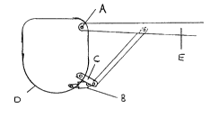
- In drawings which illustrate embodiments of the
invention, Figure 1 is the foward outline view of a high
wing fuselage structure showing a single axis pivot & a
single external strut pivot link. Figure 2 is the foward
outline view of a high wing fuselage structure showing a

.~ 2121823

Specification Soft Wing Suspension


Cont.


single axis pivot and external strut with no pivot link.
Figure 3 is the foward outline view of a fuselage struct-
ure showing a single axis pivot set back from the end of
the wing spar. Figure 4 is the foward outline view of a
low wing fuselage showing a single axis pivot with a land-
ing gear attached to the wing. Figure 5 is the foward out-
line view of a fuselage showing a multiple pivot attachm-
ent. Figure 6 is the same as figure 5 except the pivots
are all located within the fuselage. Figure 7,8,9 are
front views of a wing or stabilizor being fastened to the
aircraft showing various link geometry. Figure 10 is the
top view of the multi axis pivot showing the link inter-
connect arm. Figure 11 is a 3-D view of the multiple axis
pivot.

An airplane wing or stabilizor which is allowed to
pivot in flight requires a pivot, or several pivots, a
means to hold the wing in the desired position of it s
pivoting travel during flight, a means to limit the amount
of pivot allowed, and the means to dampen the pivoting
action. For the Purposes of simplifying all of my drawings
I have incorperated into item B, the travel stops, shock
dampening capacity and load carrying capacity (either
tension or compression). Aircraft manufacturers may choose
to do the same, or have individual items preform each task.
There are two types of pivot shown in my drawings. A sin-
gle axis pivot is where the pivoting action of the wing
is about ane axis and it is fairly simple in design. The
single axis can be at the end of the spar of the attaching
part as in figure 1,2, and 4 item A, or set back on the
spar as shown in figure 3 item A. Any of the single axis
designs require that the load carrying capacity of item B
to balance the leverage of the wing generated over pivot
A. A single axis pivot causes a large change in the dih-
edral angle of the wing when it pivots and depending on
the distance from the pivot to the edge of the fuselage,
relatively small amounts of vertical wing movement occur


.' ",'"`' ~
. . .- .

2121~2~

Specification Soft Wing Suspension


Cont.


near the fuselage. The double axis or multiple axis pivot
allow the designer much better control of wing movement
and he p to reduce the loads on item B. With the pivot
links being attached allowing two or more axis to trans-
fer wing or stabilizor loads to the airplane, item B no
longer has to support torque loads as was required with a
single pivot axis. Item B now supports only lifting and
stabilizing loads. Vertical wing movement near the fuselage
can be increased providing a smoother ride to the passen-
gers. In figure 7 you can see the angular attachment of
the pivot arms from the airplane (G) to the wing (E). The
angular attachment of the links forms an artifical pivot
point (H) which allows more wing or stabilizor tip move-
ment then wing or stabilizor root. Figure 8 shows parallel
links which allow equal tip and root movement and figure
9 shows moreroot movement and less tip movement. The piv-
ot links (C) must be joined with an interconnect brace (3)
to help keep foward, aft and any intermediate links at the
same angle so the wing tip doesn t move foward and aft.
Figure 3 and 4 show the mounting of landing gear directly
to the bottom of the wing.


Representative Drawing
A single figure which represents the drawing illustrating the invention.
Administrative Status

For a clearer understanding of the status of the application/patent presented on this page, the site Disclaimer , as well as the definitions for Patent , Administrative Status , Maintenance Fee  and Payment History  should be consulted.

Administrative Status

Title Date
Forecasted Issue Date Unavailable
(22) Filed 1994-04-21
(41) Open to Public Inspection 1995-10-22
Dead Application 1997-04-21

Abandonment History

There is no abandonment history.

Payment History

Fee Type Anniversary Year Due Date Amount Paid Paid Date
Application Fee $0.00 1994-04-21
Owners on Record

Note: Records showing the ownership history in alphabetical order.

Current Owners on Record
DAWSON, PAUL WESLEY
Past Owners on Record
None
Past Owners that do not appear in the "Owners on Record" listing will appear in other documentation within the application.
Documents

To view selected files, please enter reCAPTCHA code :


To view images, click a link in the Document Description column. To download the documents, select one or more checkboxes in the first column and then click the "Download Selected in PDF format (Zip Archive)" or the "Download Selected as Single PDF" button.

List of published and non-published patent-specific documents on the CPD .

If you have any difficulty accessing content, you can call the Client Service Centre at 1-866-997-1936 or send them an e-mail at CIPO Client Service Centre.


Document
Description 
Date
(yyyy-mm-dd) 
Number of pages   Size of Image (KB) 
Cover Page 1995-12-05 1 14
Abstract 1995-10-22 1 28
Description 1995-10-22 3 123
Claims 1995-10-22 2 28
Drawings 1995-10-22 2 35
Representative Drawing 1998-07-31 1 2