Sélection de la langue

Search

Sommaire du brevet 2121823 

Énoncé de désistement de responsabilité concernant l'information provenant de tiers

Une partie des informations de ce site Web a été fournie par des sources externes. Le gouvernement du Canada n'assume aucune responsabilité concernant la précision, l'actualité ou la fiabilité des informations fournies par les sources externes. Les utilisateurs qui désirent employer cette information devraient consulter directement la source des informations. Le contenu fourni par les sources externes n'est pas assujetti aux exigences sur les langues officielles, la protection des renseignements personnels et l'accessibilité.

Disponibilité de l'Abrégé et des Revendications

L'apparition de différences dans le texte et l'image des Revendications et de l'Abrégé dépend du moment auquel le document est publié. Les textes des Revendications et de l'Abrégé sont affichés :

  • lorsque la demande peut être examinée par le public;
  • lorsque le brevet est émis (délivrance).
(12) Demande de brevet: (11) CA 2121823
(54) Titre français: ELEMENT DE SUSPENSION D'AILE D'AVION
(54) Titre anglais: SOFT WING SUSPENSION
Statut: Réputée abandonnée et au-delà du délai pour le rétablissement - en attente de la réponse à l’avis de communication rejetée
Données bibliographiques
Abrégés

Abrégé anglais


Most aircraft currently being manufactured today use some
form of suspension system which will dampen the impact
forces of landing and bumps on the ground. None of the
airplanes manufactured today provide any means to dampen
any sudden flight loads or bumps while flying, except for
the flexing of the wing.
My invention is to provide a means to provide relative
movement between the fusealage and it?s supporting and
controling structures (wings, stabalizers) during flight.
It will also provide means to control the rate, neutral
position and amount of movement these surfaces are allowed.
By doing this the passengers in the airplane will enjoy
a smoother ride, and fatigue loads on the entire airplane
structure will be reduced. Inspection times and airframe
life could be extended as it is known that aircraft which
fly through turbulant air regularly (pipe line patrol)
have shorter inspection times and airframe life. The
dampened movement of the wing would also allow floats,
wheels or skiis to be mounted directly to the bottom of
the wing, which can now be used to absorb landing loads.

Revendications

Note : Les revendications sont présentées dans la langue officielle dans laquelle elles ont été soumises.


The embodiments of the invention in which an exclusive
property or privilege is claimed are defined as follows:
1 Any type of pivot used to attach a wing or section of
wing, or stabilizor or section of stabilizor to the
airplane, allowing independant movement of that item, which
movement is intended to allow vibrations caused by flight
or landing loads to be dampened.
2 The attachment of a shock absorbing device to an item
mounted as per claim 1.

Cont.
3 The attachment of a load carrying device (springs, gas
struts, rubber blucks...) to support the structures mounted
as per claim 1.
4 The use of links or arms between pivot points described
in claim 1 which will allow movement as illistrated in the
specification describing figure 7,8,9.
5 The use of an interconnect device to hold the pivot links
along the same pivot axis at the same angle to one another.
6 The attachment to an object mounted as per claim 1,
which will hold that object in a fixed position if required.

Description

Note : Les descriptions sont présentées dans la langue officielle dans laquelle elles ont été soumises.

~'
2121823
Specification Soft Wing Suspension
This invention relates to a shock absorbing suspension
system for airplanes during flight.
It is common in aircraft manufactured today to fasten
the wing and stabilizers solidly to the airplane fuselage
in a fixed position for flight. Any type of adjustable
wings currently designed today allow changes in sweep,
dihedral and angle of incidence, but they still hold the
wing rigidly to the fuselage providing no means for the
wing or stabilizor to move under changing flight loads.
The only type of shock absorbtion is from the wing and
stabilizors flexing. This solid type of mounting causes
all of the vibrations and stresses of flight through
turbulant air to be transferred to the fuselage and
passengers. These vibrations cause the airplane life to
decrease because of fatique stress and cause passengers
to become airsick and tired.
My invention is to use one or more pivots when mount-
-- ing the wings and stabilizors to the fuselage of an air-
plane, allowing them independant movement in flight.
This movement will allow the sudden stresses - or bumps-
caused by turbulance to be dampened before they are
transfered to the fuselage. Through the use of multiple
pivot points and pivotarms or links and limit stops, a
designer can control the exact amount of movement he wants
and allow that movement where he wants it on that wing or
stabilizor. The movement of the wing also would allow for
the installation ofmotion dampening devices (shock absorb-
ers) and a wide variety of load carrying devices such as
springs or gas charged cylinders to allow the designer
and pilot of the aircraft to select the type of ride
desired inside. Also with the wings now being able to ab-
sorb shock loads, seperate shock absorbing landing gear
systems could be removed and wheels, skiis, or floats can
be directly mounted to the wing. The wing can now absorb
landing and flight loads.
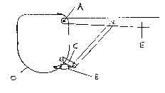
- In drawings which illustrate embodiments of the
invention, Figure 1 is the foward outline view of a high
wing fuselage structure showing a single axis pivot & a
single external strut pivot link. Figure 2 is the foward
outline view of a high wing fuselage structure showing a

.~ 2121823
Specification Soft Wing Suspension
Cont.
single axis pivot and external strut with no pivot link.
Figure 3 is the foward outline view of a fuselage struct-
ure showing a single axis pivot set back from the end of
the wing spar. Figure 4 is the foward outline view of a
low wing fuselage showing a single axis pivot with a land-
ing gear attached to the wing. Figure 5 is the foward out-
line view of a fuselage showing a multiple pivot attachm-
ent. Figure 6 is the same as figure 5 except the pivots
are all located within the fuselage. Figure 7,8,9 are
front views of a wing or stabilizor being fastened to the
aircraft showing various link geometry. Figure 10 is the
top view of the multi axis pivot showing the link inter-
connect arm. Figure 11 is a 3-D view of the multiple axis
pivot.
An airplane wing or stabilizor which is allowed to
pivot in flight requires a pivot, or several pivots, a
means to hold the wing in the desired position of it s
pivoting travel during flight, a means to limit the amount
of pivot allowed, and the means to dampen the pivoting
action. For the Purposes of simplifying all of my drawings
I have incorperated into item B, the travel stops, shock
dampening capacity and load carrying capacity (either
tension or compression). Aircraft manufacturers may choose
to do the same, or have individual items preform each task.
There are two types of pivot shown in my drawings. A sin-
gle axis pivot is where the pivoting action of the wing
is about ane axis and it is fairly simple in design. The
single axis can be at the end of the spar of the attaching
part as in figure 1,2, and 4 item A, or set back on the
spar as shown in figure 3 item A. Any of the single axis
designs require that the load carrying capacity of item B
to balance the leverage of the wing generated over pivot
A. A single axis pivot causes a large change in the dih-
edral angle of the wing when it pivots and depending on
the distance from the pivot to the edge of the fuselage,
relatively small amounts of vertical wing movement occur
.' ",'"`' ~
. . .- .

2121~2~
Specification Soft Wing Suspension
Cont.
near the fuselage. The double axis or multiple axis pivot
allow the designer much better control of wing movement
and he p to reduce the loads on item B. With the pivot
links being attached allowing two or more axis to trans-
fer wing or stabilizor loads to the airplane, item B no
longer has to support torque loads as was required with a
single pivot axis. Item B now supports only lifting and
stabilizing loads. Vertical wing movement near the fuselage
can be increased providing a smoother ride to the passen-
gers. In figure 7 you can see the angular attachment of
the pivot arms from the airplane (G) to the wing (E). The
angular attachment of the links forms an artifical pivot
point (H) which allows more wing or stabilizor tip move-
ment then wing or stabilizor root. Figure 8 shows parallel
links which allow equal tip and root movement and figure
9 shows moreroot movement and less tip movement. The piv-
ot links (C) must be joined with an interconnect brace (3)
to help keep foward, aft and any intermediate links at the
same angle so the wing tip doesn t move foward and aft.
Figure 3 and 4 show the mounting of landing gear directly
to the bottom of the wing.

Dessin représentatif
Une figure unique qui représente un dessin illustrant l'invention.
États administratifs

2024-08-01 : Dans le cadre de la transition vers les Brevets de nouvelle génération (BNG), la base de données sur les brevets canadiens (BDBC) contient désormais un Historique d'événement plus détaillé, qui reproduit le Journal des événements de notre nouvelle solution interne.

Veuillez noter que les événements débutant par « Inactive : » se réfèrent à des événements qui ne sont plus utilisés dans notre nouvelle solution interne.

Pour une meilleure compréhension de l'état de la demande ou brevet qui figure sur cette page, la rubrique Mise en garde , et les descriptions de Brevet , Historique d'événement , Taxes périodiques et Historique des paiements devraient être consultées.

Historique d'événement

Description Date
Le délai pour l'annulation est expiré 1997-04-21
Demande non rétablie avant l'échéance 1997-04-21
Réputée abandonnée - omission de répondre à un avis sur les taxes pour le maintien en état 1996-04-22
Inactive : Demande ad hoc documentée 1996-04-22
Demande publiée (accessible au public) 1995-10-22

Historique d'abandonnement

Date d'abandonnement Raison Date de rétablissement
1996-04-22
Titulaires au dossier

Les titulaires actuels et antérieures au dossier sont affichés en ordre alphabétique.

Titulaires actuels au dossier
PAUL WESLEY DAWSON
Titulaires antérieures au dossier
S.O.
Les propriétaires antérieurs qui ne figurent pas dans la liste des « Propriétaires au dossier » apparaîtront dans d'autres documents au dossier.
Documents

Pour visionner les fichiers sélectionnés, entrer le code reCAPTCHA :


Pour visualiser une image, cliquer sur un lien dans la colonne description du document. Pour télécharger l'image (les images), cliquer l'une ou plusieurs cases à cocher dans la première colonne et ensuite cliquer sur le bouton "Télécharger sélection en format PDF (archive Zip)" ou le bouton "Télécharger sélection (en un fichier PDF fusionné)".

Liste des documents de brevet publiés et non publiés sur la BDBC .

Si vous avez des difficultés à accéder au contenu, veuillez communiquer avec le Centre de services à la clientèle au 1-866-997-1936, ou envoyer un courriel au Centre de service à la clientèle de l'OPIC.


Description du
Document 
Date
(aaaa-mm-jj) 
Nombre de pages   Taille de l'image (Ko) 
Revendications 1995-10-21 2 28
Description 1995-10-21 3 123
Abrégé 1995-10-21 1 28
Dessins 1995-10-21 2 35
Dessin représentatif 1998-07-30 1 2