Language selection

Search

Patent 2126408 Summary

Third-party information liability

Some of the information on this Web page has been provided by external sources. The Government of Canada is not responsible for the accuracy, reliability or currency of the information supplied by external sources. Users wishing to rely upon this information should consult directly with the source of the information. Content provided by external sources is not subject to official languages, privacy and accessibility requirements.

Claims and Abstract availability

Any discrepancies in the text and image of the Claims and Abstract are due to differing posting times. Text of the Claims and Abstract are posted:

  • At the time the application is open to public inspection;
  • At the time of issue of the patent (grant).
(12) Patent: (11) CA 2126408
(54) English Title: MECHANISM FOR ADJUSTING THE HEIGHT OF A FRAME OF AN AGRICULTURAL IMPLEMENT RELATIVE TO A GROUNDSURFACE
(54) French Title: MECANISME POUR REGLER LA GARDE AU SOL D'UNE MACHINE AGRICOLE
Status: Expired
Bibliographic Data
(51) International Patent Classification (IPC):
  • A01B 63/14 (2006.01)
  • A01B 63/22 (2006.01)
(72) Inventors :
  • DEGELMAN, WILFRED JOHN (Canada)
  • EVANS, MILES (Canada)
(73) Owners :
  • DEGELMAN INDUSTRIES LP (Not Available)
(71) Applicants :
  • DEGELMAN INDUSTRIES LTD. (Canada)
(74) Agent: WOODRUFF, NATHAN V.
(74) Associate agent:
(45) Issued: 2000-03-14
(22) Filed Date: 1994-06-21
(41) Open to Public Inspection: 1995-12-22
Examination requested: 1997-04-18
Availability of licence: N/A
(25) Language of filing: English

Patent Cooperation Treaty (PCT): No

(30) Application Priority Data: None

Abstracts

English Abstract

A mechanism for adjusting the height of a frame of an agricultural implement relative to a groundsurface is described. A parallelogram frame is provided which includes a frame mounted member and a wheel mounting member parallel to the frame mounted member. The frame mounted member is secured in substantially vertical orientation to an end of a transverse support member of the frame of the agricultural implement. A stub axle is secured substantially perpendicularly to a face of the wheel mounting member remote from the transverse support member with a ground engaging wheel rotatably mounted on the stub axle. An expandable jack is mounted to the top of the transverse support member. Upon expansion of the jack a force is exerted upon an upper connecting member causing the parallelogram frame to pivot until a first end of the upper connecting member to which the end of the transverse support member is attached is raised relative to a second end of upper connecting member. Upon contraction of the jack a force is exerted upon the upper connecting member causing the parallelogram frame to pivot until the first end of upper connecting member to which the end of the transverse support member is attached is lowered relative to the second end of upper connecting member.


French Abstract

Un mécanisme pour régler la garde au sol d'une machine agricole est décrit. Un châssis en forme de parallélogramme est fourni qui comprend un élément monté sur le châssis et un élément de fixation de roue parallèle à l'élément monté sur le châssis. L'élément monté sur le châssis est fixé dans une orientation sensiblement verticale à l'extrémité d'un élément de soutien transversal du châssis de la machine agricole. Un demi-essieu est fixé sensiblement perpendiculairement à une face de l'élément de fixation des roues et éloigné de l'élément de soutien transversal avec une roue reposant sur le sol montée de manière pivotante sur le demi-essieu. Un vérin extensible est monté sur le dessus de l'élément de soutien transversal. Lors de l'extension du vérin, une force est exercée sur un élément de raccordement supérieur permettant au châssis en forme de parallélogramme de pivoter jusqu'à ce qu'une première extrémité de l'élément de raccordement supérieur auquel s'attache l'extrémité de l'élément de soutien transversal soit élevée par rapport à une deuxième extrémité de l'élément de raccordement supérieur. Lors de la contraction du vérin, une force est exercée sur l'élément de raccordement supérieur permettant au châssis en forme de parallélogramme de pivoter jusqu'à ce qu'une première extrémité de l'élément de raccordement supérieur auquel s'attache l'extrémité de l'élément de soutien transversal soit abaissée par rapport à la seconde extrémité de l'élément de raccordement supérieur.

Claims

Note: Claims are shown in the official language in which they were submitted.


5
THE EMBODIMENTS OF THE INVENTION IN WHICH THE EXCLUSIVE
PROPERTY OR PRIVILEGE IS CLAIMED ARE DEFINED AS FOLLOWS:

1. A mechanism for adjusting the height of a frame of an
agricultural implement relative to a ground surface,
comprising in combination:
a ground engaging wheel;
a transverse support member of the frame of the
agricultural implement, the transverse support member having
a top and an end;
a parallelogram frame including a frame mounted member,
a wheel mounting member parallel to the frame mounted member,
an upper connecting member having a first end pivotally
connected to the frame mounted member and a second end
connected to the wheel mounting member, and a lower connecting
member parallel to the upper connecting member and pivotally
connected to the frame mounted member and the wheel mounting
member, the frame mounted member being secured in
substantially vertical orientation to the end of the
transverse support member, a stub axle being secured in a
fixed position directly to the wheel mounting member with the
stub axle extending substantially perpendicularly to a face of
the wheel mounting member remote from the transverse support
member with the ground engaging wheel rotatably mounted on the
stub axle; and
an expandable jack having a first end and a second end,
the first end being mounted to the top of the transverse
support member and the second end being attached to a
projection on the upper connecting member such that upon
expansion of the jack a force is exerted upon the upper
connecting member causing the parallelogram frame to pivot
until the first end of upper connecting member to which the
end of the transverse support member is attached is raised
relative to the second end of upper connecting member and upon
contraction of the jack a force is exerted upon the upper
connecting member causing the parallelogram frame to pivot
until the first end of upper connecting member to which the


6
end of the transverse support member is attached is lowered
relative to the second end of upper connecting member.
2. The mechanism for adjusting the height of a frame of an
agricultural implement relative to a ground surface as defined
in Claim 1, wherein the frame mounted member, the wheel
mounting member, the upper connecting member and the lower
connecting member are substantially equal in length.

Description

Note: Descriptions are shown in the official language in which they were submitted.


- 2126408
The present invention relates to a mechanism for adjusting
the height of a frame of an agricultural implement relative to
a groundsurface.


BACKGROWD OF THE INVENTION

There are a variety of alternative mechanisms for
adjusting the height of a frame of an agricultural implement
relative to a groundsurface. The problem with most of such
mechanisms is that they are unduly complex, which makes them
more expensive and increases maintenance costs.


SU~$~RY OF THE INVENTION

What is required is a comparatively simple mechanism for
adjusting the height of a frame of an agricultural implement
relative to a groundsurface.

According to the present invention there is provided a
mechanism for adjusting the height of a frame of an
agricultural implement relative to a groundsurface which
includes, in combination, a ground engaging wheel and a
transverse support member of a frame of an agricultural
implement. The transverse support member has a top and an end.
A parallelogram frame is provided which includes a frame
mounted member, a wheel mounting member parallel to the frame
mounted member, an upper connecting member having a first end
pivotally connected to the frame mounted member and a second
end connected to the wheel mounting member, and a lower
connecting member parallel to the upper connecting member and
pivotally connected to the frame mounted member and the wheel
mounting member. The frame mounted member is secured in
substantially vertical orientation to the end of the transverse
support member. A stub axle is secured substantially
perpendicularly to a face of the wheel mounting member remote
from the transverse support member with the ground engaging

2126~08


wheel rotatably mounted on the stub axle. An expandable jack
is provided having a first end and a second end. The first end
is mounted to the top of the transverse support member. The
second end is attached to a projection on the upper connecting
member. Upon expansion of the jack a force is exerted upon the
upper connecting member causing the parallelogram frame to
pivot until the first end of upper connecting member to which
the end of the transverse support member is attached is raised
relative to the second end of upper connecting member. Upon
contraction of the jack a force is exerted upon the upper
connecting member causing the parallelogram frame to pivot
until the first end of upper connecting member to which the end
of the transverse support member is attached is lowered
relative to the second end of upper connecting member.

BRIEF DESCRIPTION OF THE DRAWINGS

These and other features of the invention will become more
apparent from the following description in which reference is
made to the appended drawings, wherein:
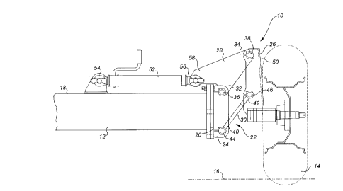
FIGURE 1 is a front elevation view of a mechanism for
adjusting the height of a frame of an agricultural implement
constructed in accordance with the teachings of the present
invention in a lowered position.
FIGURE 2 is a front elevation view of a mechanism for
adjusting the height of a frame of an agricultural implement
constructed in accordance with the teachings of the present
invention in a raised position.

DE~ATTFn DESCRIPTION OF THE ~K~r-~KK~v EMBODIMENT

The preferred embodiment, a mechanism for adjusting the
height of a frame of an agricultural implement relative to a
groundsurface generally identified by reference numeral 10,
will now be described with reference to FIGURES 1 and 2.

2126408


Referring to FIGURES 1 and 2, there is illustrated a
transverse support member 12 of a frame of an agricultural
implement (not shown) and a ground engaging wheel 14 that rests
upon a groundsurface 16. Transverse support member 12 has a
top 18 and an end 20. A parallelogram frame, generally
indicated by reference numeral 22, is provided which includes
four members: a frame mounted member 24, a wheel mounting
member 26, an upper connecting member 28 and a lower connecting
member 30. Wheel mounting member 26 is parallel to frame
mounted member 24. Upper connecting member 28 has a first end
32 and a second end 34. First end 32 is pivotally connected
at pivotal connection 36 to frame mounted member 24. Second
end 34 is pivotally connected at pivotal connection 38 to wheel
mounting member 26. Lower connecting member 30 has a first end
40 and a second end 42. Lower connecting member 30 is parallel
to upper connecting member 28. First end 40 is pivotally
connected at pivotal connection 44 to frame mounted member 24.
Second end 42 is pivotally connected at pivotal connection 46
to wheel mounting member 26. Frame mounted member 24 is
secured in substantially vertical orientation to end 20 of
transverse support member 12. A stub axle 48 is secured
substantially perpendicularly to a face 50 of wheel mounting
member 26 remote from end 20 of transverse support member 12.
Ground engaging wheel 14 is rotatably mounted on stub axle 48.
An expandable screw jack 52 is provided having a first end 54
and a second end 56. First end 54 is mounted to top 18 of
transverse support member 12. Second end 56 is attached to a
projection 58 on upper connecting member 28.
The use and operation of mechanism 10 will now be
described with reference to FIGURES 1 and 2. Referring to
FIGURE 2, upon expansion of screw jack 52 a force is exerted
upon upper connecting member 28 causing parallelogram frame 22
to pivot until first end 32 of upper connecting member 28 to
which end 20 of transverse support member 12 is attached is
raised relative to second end 34 of upper connecting member 28.

2l26~o8

Referring to FIGURE 1, upon contraction of screw jack 52 a
force is exerted upon upper connecting member 28 causing
parallelogram frame 22 to pivot until first end 32 of upper
connecting member 28 to which end 20 of transverse support
member 12 is attached is lowered relative to second end 34 of
upper connecting member 28.

It will be apparent to one skilled in the art that
modifications may be made to the illustrated embodiment without
departing from the spirit and scope of the invention as
hereinafter defined in the Claims.

Representative Drawing
A single figure which represents the drawing illustrating the invention.
Administrative Status

For a clearer understanding of the status of the application/patent presented on this page, the site Disclaimer , as well as the definitions for Patent , Administrative Status , Maintenance Fee  and Payment History  should be consulted.

Administrative Status

Title Date
Forecasted Issue Date 2000-03-14
(22) Filed 1994-06-21
(41) Open to Public Inspection 1995-12-22
Examination Requested 1997-04-18
(45) Issued 2000-03-14
Expired 2014-06-23

Abandonment History

There is no abandonment history.

Payment History

Fee Type Anniversary Year Due Date Amount Paid Paid Date
Application Fee $0.00 1994-06-21
Registration of a document - section 124 $0.00 1995-09-28
Maintenance Fee - Application - New Act 2 1996-06-21 $50.00 1996-04-11
Request for Examination $400.00 1997-04-18
Maintenance Fee - Application - New Act 3 1997-06-23 $100.00 1997-04-18
Maintenance Fee - Application - New Act 4 1998-06-22 $100.00 1998-05-26
Maintenance Fee - Application - New Act 5 1999-06-21 $150.00 1999-05-21
Final Fee $300.00 1999-11-04
Maintenance Fee - Patent - New Act 6 2000-06-21 $150.00 2000-06-06
Maintenance Fee - Patent - New Act 7 2001-06-21 $150.00 2001-05-24
Maintenance Fee - Patent - New Act 8 2002-06-21 $150.00 2002-06-13
Maintenance Fee - Patent - New Act 9 2003-06-23 $150.00 2003-06-12
Maintenance Fee - Patent - New Act 10 2004-06-21 $250.00 2004-04-20
Maintenance Fee - Patent - New Act 11 2005-06-21 $250.00 2005-04-13
Maintenance Fee - Patent - New Act 12 2006-06-21 $250.00 2006-06-21
Expired 2019 - Corrective payment/Section 78.6 $250.00 2007-01-31
Maintenance Fee - Patent - New Act 13 2007-06-21 $450.00 2008-04-02
Maintenance Fee - Patent - New Act 14 2008-06-23 $250.00 2008-04-02
Maintenance Fee - Patent - New Act 15 2009-06-22 $450.00 2009-04-17
Maintenance Fee - Patent - New Act 16 2010-06-21 $450.00 2010-04-23
Maintenance Fee - Patent - New Act 17 2011-06-21 $450.00 2011-05-02
Maintenance Fee - Patent - New Act 18 2012-06-21 $450.00 2012-03-26
Maintenance Fee - Patent - New Act 19 2013-06-21 $450.00 2013-04-26
Registration of a document - section 124 2020-04-03 $100.00 2020-04-03
Owners on Record

Note: Records showing the ownership history in alphabetical order.

Current Owners on Record
DEGELMAN INDUSTRIES LP
Past Owners on Record
DEGELMAN INDUSTRIES LTD.
DEGELMAN, WILFRED JOHN
EVANS, MILES
Past Owners that do not appear in the "Owners on Record" listing will appear in other documentation within the application.
Documents

To view selected files, please enter reCAPTCHA code :


To view images, click a link in the Document Description column. To download the documents, select one or more checkboxes in the first column and then click the "Download Selected in PDF format (Zip Archive)" or the "Download Selected as Single PDF" button.

List of published and non-published patent-specific documents on the CPD .

If you have any difficulty accessing content, you can call the Client Service Centre at 1-866-997-1936 or send them an e-mail at CIPO Client Service Centre.


Document
Description 
Date
(yyyy-mm-dd) 
Number of pages   Size of Image (KB) 
Cover Page 2000-02-01 1 46
Cover Page 1996-04-03 1 17
Abstract 1995-12-22 1 38
Description 1995-12-22 4 167
Claims 1995-12-22 1 54
Drawings 1995-12-22 2 34
Representative Drawing 2000-02-01 1 7
Representative Drawing 1998-05-25 1 15
Claims 1997-12-04 2 62
Drawings 1997-12-04 2 30
Fees 2005-04-13 1 28
Correspondence 1999-11-04 1 39
Prosecution-Amendment 1999-11-04 1 39
Fees 2003-06-12 1 28
Correspondence 2007-05-09 1 12
Assignment 1994-06-21 11 376
Prosecution-Amendment 1997-04-18 7 250
Fees 2002-06-13 1 29
Fees 1998-05-26 1 39
Fees 1999-05-21 1 34
Fees 2004-04-20 1 29
Fees 2006-06-21 1 26
Correspondence 2011-04-28 1 12
Prosecution-Amendment 2007-01-31 1 32
Fees 2008-04-02 1 33
Fees 2009-04-17 1 201
Fees 2010-04-23 1 29
Correspondence 2011-03-31 3 133
Correspondence 2011-05-03 1 19
Fees 1997-04-18 1 39
Fees 1996-04-11 1 42