Sélection de la langue

Search

Sommaire du brevet 2126408 

Énoncé de désistement de responsabilité concernant l'information provenant de tiers

Une partie des informations de ce site Web a été fournie par des sources externes. Le gouvernement du Canada n'assume aucune responsabilité concernant la précision, l'actualité ou la fiabilité des informations fournies par les sources externes. Les utilisateurs qui désirent employer cette information devraient consulter directement la source des informations. Le contenu fourni par les sources externes n'est pas assujetti aux exigences sur les langues officielles, la protection des renseignements personnels et l'accessibilité.

Disponibilité de l'Abrégé et des Revendications

L'apparition de différences dans le texte et l'image des Revendications et de l'Abrégé dépend du moment auquel le document est publié. Les textes des Revendications et de l'Abrégé sont affichés :

  • lorsque la demande peut être examinée par le public;
  • lorsque le brevet est émis (délivrance).
(12) Brevet: (11) CA 2126408
(54) Titre français: MECANISME POUR REGLER LA GARDE AU SOL D'UNE MACHINE AGRICOLE
(54) Titre anglais: MECHANISM FOR ADJUSTING THE HEIGHT OF A FRAME OF AN AGRICULTURAL IMPLEMENT RELATIVE TO A GROUNDSURFACE
Statut: Périmé
Données bibliographiques
(51) Classification internationale des brevets (CIB):
  • A01B 63/14 (2006.01)
  • A01B 63/22 (2006.01)
(72) Inventeurs :
  • DEGELMAN, WILFRED JOHN (Canada)
  • EVANS, MILES (Canada)
(73) Titulaires :
  • DEGELMAN INDUSTRIES LP (Non disponible)
(71) Demandeurs :
  • DEGELMAN INDUSTRIES LTD. (Canada)
(74) Agent: WOODRUFF, NATHAN V.
(74) Co-agent:
(45) Délivré: 2000-03-14
(22) Date de dépôt: 1994-06-21
(41) Mise à la disponibilité du public: 1995-12-22
Requête d'examen: 1997-04-18
Licence disponible: S.O.
(25) Langue des documents déposés: Anglais

Traité de coopération en matière de brevets (PCT): Non

(30) Données de priorité de la demande: S.O.

Abrégés

Abrégé français

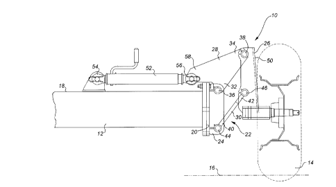
Un mécanisme pour régler la garde au sol d'une machine agricole est décrit. Un châssis en forme de parallélogramme est fourni qui comprend un élément monté sur le châssis et un élément de fixation de roue parallèle à l'élément monté sur le châssis. L'élément monté sur le châssis est fixé dans une orientation sensiblement verticale à l'extrémité d'un élément de soutien transversal du châssis de la machine agricole. Un demi-essieu est fixé sensiblement perpendiculairement à une face de l'élément de fixation des roues et éloigné de l'élément de soutien transversal avec une roue reposant sur le sol montée de manière pivotante sur le demi-essieu. Un vérin extensible est monté sur le dessus de l'élément de soutien transversal. Lors de l'extension du vérin, une force est exercée sur un élément de raccordement supérieur permettant au châssis en forme de parallélogramme de pivoter jusqu'à ce qu'une première extrémité de l'élément de raccordement supérieur auquel s'attache l'extrémité de l'élément de soutien transversal soit élevée par rapport à une deuxième extrémité de l'élément de raccordement supérieur. Lors de la contraction du vérin, une force est exercée sur l'élément de raccordement supérieur permettant au châssis en forme de parallélogramme de pivoter jusqu'à ce qu'une première extrémité de l'élément de raccordement supérieur auquel s'attache l'extrémité de l'élément de soutien transversal soit abaissée par rapport à la seconde extrémité de l'élément de raccordement supérieur.


Abrégé anglais

A mechanism for adjusting the height of a frame of an agricultural implement relative to a groundsurface is described. A parallelogram frame is provided which includes a frame mounted member and a wheel mounting member parallel to the frame mounted member. The frame mounted member is secured in substantially vertical orientation to an end of a transverse support member of the frame of the agricultural implement. A stub axle is secured substantially perpendicularly to a face of the wheel mounting member remote from the transverse support member with a ground engaging wheel rotatably mounted on the stub axle. An expandable jack is mounted to the top of the transverse support member. Upon expansion of the jack a force is exerted upon an upper connecting member causing the parallelogram frame to pivot until a first end of the upper connecting member to which the end of the transverse support member is attached is raised relative to a second end of upper connecting member. Upon contraction of the jack a force is exerted upon the upper connecting member causing the parallelogram frame to pivot until the first end of upper connecting member to which the end of the transverse support member is attached is lowered relative to the second end of upper connecting member.

Revendications

Note : Les revendications sont présentées dans la langue officielle dans laquelle elles ont été soumises.


5
THE EMBODIMENTS OF THE INVENTION IN WHICH THE EXCLUSIVE
PROPERTY OR PRIVILEGE IS CLAIMED ARE DEFINED AS FOLLOWS:

1. A mechanism for adjusting the height of a frame of an
agricultural implement relative to a ground surface,
comprising in combination:
a ground engaging wheel;
a transverse support member of the frame of the
agricultural implement, the transverse support member having
a top and an end;
a parallelogram frame including a frame mounted member,
a wheel mounting member parallel to the frame mounted member,
an upper connecting member having a first end pivotally
connected to the frame mounted member and a second end
connected to the wheel mounting member, and a lower connecting
member parallel to the upper connecting member and pivotally
connected to the frame mounted member and the wheel mounting
member, the frame mounted member being secured in
substantially vertical orientation to the end of the
transverse support member, a stub axle being secured in a
fixed position directly to the wheel mounting member with the
stub axle extending substantially perpendicularly to a face of
the wheel mounting member remote from the transverse support
member with the ground engaging wheel rotatably mounted on the
stub axle; and
an expandable jack having a first end and a second end,
the first end being mounted to the top of the transverse
support member and the second end being attached to a
projection on the upper connecting member such that upon
expansion of the jack a force is exerted upon the upper
connecting member causing the parallelogram frame to pivot
until the first end of upper connecting member to which the
end of the transverse support member is attached is raised
relative to the second end of upper connecting member and upon
contraction of the jack a force is exerted upon the upper
connecting member causing the parallelogram frame to pivot
until the first end of upper connecting member to which the


6
end of the transverse support member is attached is lowered
relative to the second end of upper connecting member.
2. The mechanism for adjusting the height of a frame of an
agricultural implement relative to a ground surface as defined
in Claim 1, wherein the frame mounted member, the wheel
mounting member, the upper connecting member and the lower
connecting member are substantially equal in length.

Description

Note : Les descriptions sont présentées dans la langue officielle dans laquelle elles ont été soumises.


- 2126408
The present invention relates to a mechanism for adjusting
the height of a frame of an agricultural implement relative to
a groundsurface.


BACKGROWD OF THE INVENTION

There are a variety of alternative mechanisms for
adjusting the height of a frame of an agricultural implement
relative to a groundsurface. The problem with most of such
mechanisms is that they are unduly complex, which makes them
more expensive and increases maintenance costs.


SU~$~RY OF THE INVENTION

What is required is a comparatively simple mechanism for
adjusting the height of a frame of an agricultural implement
relative to a groundsurface.

According to the present invention there is provided a
mechanism for adjusting the height of a frame of an
agricultural implement relative to a groundsurface which
includes, in combination, a ground engaging wheel and a
transverse support member of a frame of an agricultural
implement. The transverse support member has a top and an end.
A parallelogram frame is provided which includes a frame
mounted member, a wheel mounting member parallel to the frame
mounted member, an upper connecting member having a first end
pivotally connected to the frame mounted member and a second
end connected to the wheel mounting member, and a lower
connecting member parallel to the upper connecting member and
pivotally connected to the frame mounted member and the wheel
mounting member. The frame mounted member is secured in
substantially vertical orientation to the end of the transverse
support member. A stub axle is secured substantially
perpendicularly to a face of the wheel mounting member remote
from the transverse support member with the ground engaging

2126~08


wheel rotatably mounted on the stub axle. An expandable jack
is provided having a first end and a second end. The first end
is mounted to the top of the transverse support member. The
second end is attached to a projection on the upper connecting
member. Upon expansion of the jack a force is exerted upon the
upper connecting member causing the parallelogram frame to
pivot until the first end of upper connecting member to which
the end of the transverse support member is attached is raised
relative to the second end of upper connecting member. Upon
contraction of the jack a force is exerted upon the upper
connecting member causing the parallelogram frame to pivot
until the first end of upper connecting member to which the end
of the transverse support member is attached is lowered
relative to the second end of upper connecting member.

BRIEF DESCRIPTION OF THE DRAWINGS

These and other features of the invention will become more
apparent from the following description in which reference is
made to the appended drawings, wherein:
FIGURE 1 is a front elevation view of a mechanism for
adjusting the height of a frame of an agricultural implement
constructed in accordance with the teachings of the present
invention in a lowered position.
FIGURE 2 is a front elevation view of a mechanism for
adjusting the height of a frame of an agricultural implement
constructed in accordance with the teachings of the present
invention in a raised position.

DE~ATTFn DESCRIPTION OF THE ~K~r-~KK~v EMBODIMENT

The preferred embodiment, a mechanism for adjusting the
height of a frame of an agricultural implement relative to a
groundsurface generally identified by reference numeral 10,
will now be described with reference to FIGURES 1 and 2.

2126408


Referring to FIGURES 1 and 2, there is illustrated a
transverse support member 12 of a frame of an agricultural
implement (not shown) and a ground engaging wheel 14 that rests
upon a groundsurface 16. Transverse support member 12 has a
top 18 and an end 20. A parallelogram frame, generally
indicated by reference numeral 22, is provided which includes
four members: a frame mounted member 24, a wheel mounting
member 26, an upper connecting member 28 and a lower connecting
member 30. Wheel mounting member 26 is parallel to frame
mounted member 24. Upper connecting member 28 has a first end
32 and a second end 34. First end 32 is pivotally connected
at pivotal connection 36 to frame mounted member 24. Second
end 34 is pivotally connected at pivotal connection 38 to wheel
mounting member 26. Lower connecting member 30 has a first end
40 and a second end 42. Lower connecting member 30 is parallel
to upper connecting member 28. First end 40 is pivotally
connected at pivotal connection 44 to frame mounted member 24.
Second end 42 is pivotally connected at pivotal connection 46
to wheel mounting member 26. Frame mounted member 24 is
secured in substantially vertical orientation to end 20 of
transverse support member 12. A stub axle 48 is secured
substantially perpendicularly to a face 50 of wheel mounting
member 26 remote from end 20 of transverse support member 12.
Ground engaging wheel 14 is rotatably mounted on stub axle 48.
An expandable screw jack 52 is provided having a first end 54
and a second end 56. First end 54 is mounted to top 18 of
transverse support member 12. Second end 56 is attached to a
projection 58 on upper connecting member 28.
The use and operation of mechanism 10 will now be
described with reference to FIGURES 1 and 2. Referring to
FIGURE 2, upon expansion of screw jack 52 a force is exerted
upon upper connecting member 28 causing parallelogram frame 22
to pivot until first end 32 of upper connecting member 28 to
which end 20 of transverse support member 12 is attached is
raised relative to second end 34 of upper connecting member 28.

2l26~o8

Referring to FIGURE 1, upon contraction of screw jack 52 a
force is exerted upon upper connecting member 28 causing
parallelogram frame 22 to pivot until first end 32 of upper
connecting member 28 to which end 20 of transverse support
member 12 is attached is lowered relative to second end 34 of
upper connecting member 28.

It will be apparent to one skilled in the art that
modifications may be made to the illustrated embodiment without
departing from the spirit and scope of the invention as
hereinafter defined in the Claims.

Dessin représentatif
Une figure unique qui représente un dessin illustrant l'invention.
États administratifs

Pour une meilleure compréhension de l'état de la demande ou brevet qui figure sur cette page, la rubrique Mise en garde , et les descriptions de Brevet , États administratifs , Taxes périodiques et Historique des paiements devraient être consultées.

États administratifs

Titre Date
Date de délivrance prévu 2000-03-14
(22) Dépôt 1994-06-21
(41) Mise à la disponibilité du public 1995-12-22
Requête d'examen 1997-04-18
(45) Délivré 2000-03-14
Expiré 2014-06-23

Historique d'abandonnement

Il n'y a pas d'historique d'abandonnement

Historique des paiements

Type de taxes Anniversaire Échéance Montant payé Date payée
Le dépôt d'une demande de brevet 0,00 $ 1994-06-21
Enregistrement de documents 0,00 $ 1995-09-28
Taxe de maintien en état - Demande - nouvelle loi 2 1996-06-21 50,00 $ 1996-04-11
Requête d'examen 400,00 $ 1997-04-18
Taxe de maintien en état - Demande - nouvelle loi 3 1997-06-23 100,00 $ 1997-04-18
Taxe de maintien en état - Demande - nouvelle loi 4 1998-06-22 100,00 $ 1998-05-26
Taxe de maintien en état - Demande - nouvelle loi 5 1999-06-21 150,00 $ 1999-05-21
Taxe finale 300,00 $ 1999-11-04
Taxe de maintien en état - brevet - nouvelle loi 6 2000-06-21 150,00 $ 2000-06-06
Taxe de maintien en état - brevet - nouvelle loi 7 2001-06-21 150,00 $ 2001-05-24
Taxe de maintien en état - brevet - nouvelle loi 8 2002-06-21 150,00 $ 2002-06-13
Taxe de maintien en état - brevet - nouvelle loi 9 2003-06-23 150,00 $ 2003-06-12
Taxe de maintien en état - brevet - nouvelle loi 10 2004-06-21 250,00 $ 2004-04-20
Taxe de maintien en état - brevet - nouvelle loi 11 2005-06-21 250,00 $ 2005-04-13
Taxe de maintien en état - brevet - nouvelle loi 12 2006-06-21 250,00 $ 2006-06-21
Expiré 2019 - Paiement rectificatif/L'article 78.6 250,00 $ 2007-01-31
Taxe de maintien en état - brevet - nouvelle loi 13 2007-06-21 450,00 $ 2008-04-02
Taxe de maintien en état - brevet - nouvelle loi 14 2008-06-23 250,00 $ 2008-04-02
Taxe de maintien en état - brevet - nouvelle loi 15 2009-06-22 450,00 $ 2009-04-17
Taxe de maintien en état - brevet - nouvelle loi 16 2010-06-21 450,00 $ 2010-04-23
Taxe de maintien en état - brevet - nouvelle loi 17 2011-06-21 450,00 $ 2011-05-02
Taxe de maintien en état - brevet - nouvelle loi 18 2012-06-21 450,00 $ 2012-03-26
Taxe de maintien en état - brevet - nouvelle loi 19 2013-06-21 450,00 $ 2013-04-26
Enregistrement de documents 2020-04-03 100,00 $ 2020-04-03
Titulaires au dossier

Les titulaires actuels et antérieures au dossier sont affichés en ordre alphabétique.

Titulaires actuels au dossier
DEGELMAN INDUSTRIES LP
Titulaires antérieures au dossier
DEGELMAN INDUSTRIES LTD.
DEGELMAN, WILFRED JOHN
EVANS, MILES
Les propriétaires antérieurs qui ne figurent pas dans la liste des « Propriétaires au dossier » apparaîtront dans d'autres documents au dossier.
Documents

Pour visionner les fichiers sélectionnés, entrer le code reCAPTCHA :


Pour visualiser une image, cliquer sur un lien dans la colonne description du document. Pour télécharger l'image (les images), cliquer l'une ou plusieurs cases à cocher dans la première colonne et ensuite cliquer sur le bouton "Télécharger sélection en format PDF (archive Zip)" ou le bouton "Télécharger sélection (en un fichier PDF fusionné)".

Liste des documents de brevet publiés et non publiés sur la BDBC .

Si vous avez des difficultés à accéder au contenu, veuillez communiquer avec le Centre de services à la clientèle au 1-866-997-1936, ou envoyer un courriel au Centre de service à la clientèle de l'OPIC.


Description du
Document 
Date
(yyyy-mm-dd) 
Nombre de pages   Taille de l'image (Ko) 
Page couverture 2000-02-01 1 46
Page couverture 1996-04-03 1 17
Abrégé 1995-12-22 1 38
Description 1995-12-22 4 167
Revendications 1995-12-22 1 54
Dessins 1995-12-22 2 34
Dessins représentatifs 2000-02-01 1 7
Dessins représentatifs 1998-05-25 1 15
Revendications 1997-12-04 2 62
Dessins 1997-12-04 2 30
Taxes 2005-04-13 1 28
Correspondance 1999-11-04 1 39
Poursuite-Amendment 1999-11-04 1 39
Taxes 2003-06-12 1 28
Correspondance 2007-05-09 1 12
Cession 1994-06-21 11 376
Poursuite-Amendment 1997-04-18 7 250
Taxes 2002-06-13 1 29
Taxes 1998-05-26 1 39
Taxes 1999-05-21 1 34
Taxes 2004-04-20 1 29
Taxes 2006-06-21 1 26
Correspondance 2011-04-28 1 12
Poursuite-Amendment 2007-01-31 1 32
Taxes 2008-04-02 1 33
Taxes 2009-04-17 1 201
Taxes 2010-04-23 1 29
Correspondance 2011-03-31 3 133
Correspondance 2011-05-03 1 19
Taxes 1997-04-18 1 39
Taxes 1996-04-11 1 42