Language selection

Search

Patent 2134158 Summary

Third-party information liability

Some of the information on this Web page has been provided by external sources. The Government of Canada is not responsible for the accuracy, reliability or currency of the information supplied by external sources. Users wishing to rely upon this information should consult directly with the source of the information. Content provided by external sources is not subject to official languages, privacy and accessibility requirements.

Claims and Abstract availability

Any discrepancies in the text and image of the Claims and Abstract are due to differing posting times. Text of the Claims and Abstract are posted:

  • At the time the application is open to public inspection;
  • At the time of issue of the patent (grant).
(12) Patent: (11) CA 2134158
(54) English Title: ELECTRICAL CABLE CONNECTOR
(54) French Title: CONNECTEUR ELECTRIQUE POUR CABLES
Status: Expired
Bibliographic Data
(51) International Patent Classification (IPC):
  • H01R 4/18 (2006.01)
  • H01R 4/48 (2006.01)
  • H01R 4/50 (2006.01)
(72) Inventors :
  • DINIZ, MILTON EGAS (Brazil)
  • SORIANO, ALEXANDRE MARTINEZ (Brazil)
(73) Owners :
  • THE WHITAKER CORPORATION (United States of America)
(71) Applicants :
  • THE WHITAKER CORPORATION (United States of America)
(74) Agent: SMART & BIGGAR
(74) Associate agent:
(45) Issued: 2000-07-04
(22) Filed Date: 1994-10-24
(41) Open to Public Inspection: 1995-05-17
Examination requested: 1996-10-10
Availability of licence: N/A
(25) Language of filing: English

Patent Cooperation Treaty (PCT): No

(30) Application Priority Data:
Application No. Country/Territory Date
MU 7302209-8 Brazil 1993-11-16
MU 7302224-1 Brazil 1993-11-22

Abstracts

English Abstract

An electrical connector (1') having a generally C-shaped member (2') for electrically connecting wires (30') with a wedge member (12'). The C-shaped member (2') comprises radially arranged recesses (7') and holding teeth (10') which are adapted to provide tensile strength to the wedge member (12') for retaining the wires (30'). Indicia marks (A,B) are provided for correct sizing of the connector relative to the wires (30'). Figure 6.


French Abstract

Un connecteur électrique (1') possédant un élément en forme générale de C (2') pour fils de raccordement électrique (30') possédant un élément en coin (12'). L'élément en forme de C (2') comprend des évidements à disposition radiale (7') ainsi que des dents de fixation (10') adaptées pour exercer une résistance à la traction sur l'élément en coin (12') pour la fixation des fils (30'). Des repères (A,B) sont prévus pour assurer le dimensionnement approprié du connecteur relativement aux fils (30'). Figure 6.

Claims

Note: Claims are shown in the official language in which they were submitted.


-8-

Claims

1. An electrical connector having a generally
C-shaped member for electrically connecting wires with a
wedge member, the electrical connector comprising:
the C-shaped member includes radially arranged
recesses and holding teeth which are adapted to provide
tensile strength to the wedge member for retaining the
wires.
2. The electrical connector of claim 1, wherein the
radially arranged recesses generally extend completely
across the C-shaped member.
3. The electrical connector of claim 1, wherein the
C-shaped member is made of stamped and formed sheet metal.
4. The electrical connector of claim 1, wherein the
holding teeth are disposed between the radially arranged
recesses for engagement with the wires.
5. The electrical connector of claim 1, wherein at
least two indicia marks are provided on either of the
C-shaped member or the wedge member.

Description

Note: Descriptions are shown in the official language in which they were submitted.


Image


213~1~8
-,
- 2 -
applied to new or used connectors, both in the C-shaped
outer member and in the second wedge type inner member.
The problems of the known connectors are overcome by
providing an electrical cable connector which has a first
C-shaped element and a second wedge shaped element, each
capable of retaining electric cables, the first and second
elements being secured by folding flexible sheet metal.
The first C-shaped element has beaded flanges at its loose
ends, and, on the bottom part, an orifice suitable for
fitting a ridge provided on the rear part of the second
wedge type element, characterized by the fact that at
least two marks are foreseen in at least one of the
components.
An additional purpose of the present invention is to
provide teeth arranged in the C-Shaped member, in a place
where it is permitted that the teeth be spaced apart along
the length of the C-shaped member, thus permitting an
increase of the tensile strength of the connecting cables.
The present invention will now be described with the
reference to the accompanying drawings, in which:
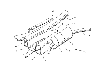
Figure 1 is a perspective view of the top part of the
connector assembly showing the first C-shaped element, the
electric cable and the second wedge type element being
wedged in to form the connector assembly.
Figure 2 is a perspective view of the bottom part of
the connector assembly which also shows the wedge type
element being inserted in the C shaped element.
15774 CA

2~.~4158
.:,
Figure 3 is a perspective view showing the C-shaped
member of the connector.
Figure 4 is a perspective view showing a sectioned
portion of the C-shaped member Figure 3 taken along line
4-4 of Figure 3.
Figure 5 is a frontal perspective view showing the
present invention in an assembled state.
Figure 6 is a perspective view of the assembled
connector, showing the cables arranged in the ocnnector
assembly.
Referring to Figures 1-2, one can determine the
connector assembly 1 comprised of a first C-shaped outer

21341~~
- 4 -
7 of C-shaped element 2 to clamp the cables 30 in the
connector assembly.
With the wedge type connectors a great variety of
combinations of conductor cable are made possible, being
limited solely to the sum of the minimum and maximum
conductor combinations, varying in accordance with a
specific cable diameter for each type of conductor.
The present invention has the purpose of providing an
alternative arrangement to the known connectors, which
will permit the technician to determine which is the
correct type of connector for an as yet unknown
arrangement in conductor cables, without damaging the
connectors (as it will not be necessary to assemble them
beforehand) .
It is possible to determine the type of connector
without previously assembling the connectors by the
incorporation of marks, preferably two already pre-
determined ones, in the C-shaped element 2, in the wedge
type element 3, or in both of them.
The marks may be made in the first and second
elements of the connectors during their manufacture or
later, and they may be superficial marks such as obtained
by painting, center punching, or any other means.
As is shown in Figures 1 and 2, the position of mark
A indicates the limit of acceptance of the connector in
accordance with the maximum sum of combinations of the
cable diameters. The position of mark "B" indicates the
15774 CA


l_ \
2134158
limit of acceptance of the minimum sum of the combination
of cables.
With marks A and B it is possible for the technician
to check, before applying the connector, whether the type
of connector chosen is correct, without risk of utilizing
an unsuitable connector.
As a practical example it may be cited that, as seen
from Figure 1, the fact that the frontal part of the wedge
is situated between marks A and B indicates that the sum
of the diameters of the conductor cables is within the
specific maximum and minimum limits for this type of
connector. Marks A and B are foreseen on both free edges
4 of the first C-shaped element 2.
As mentioned previously, marks A and B may
alternatively be made in the second wedge type element 3
(see Figure 2) for the purpose of aiding the installer to
visualize the assembly of the connector when seen from the
other side of same.
In a second embodiment, as shown in Figure 2, the
rear part of the C-shaped element 2 is placed between ,....
marks A and B, which indicates that the sum of the
diameters of the conductor cables is within a specific
minimum and maximum limit for the chosen connector.
Another embodiment of the present invention is shown
in Figures 3-6, Connector 1' comprises two pieces which
fit together to secure conductor cables 30' between them.
15774 CA


2134~.~8
- 6 -
One of the pieces is a member 2' of generally C-form which
is stamped and formed from a sheet, usually from sheet
metal, which is bent in the shape of a "C'°. In the bottom
portion 3' is provided a ramp 4' adjacent to an opening
5'.
Receptacle 2' has at least two radially arranged
recesses 7' forming inwardly directed channels 8 and
outwardly directed protuberances 9'.
The inner portion of receptacle 2' is provided with
a plurality of holding teeth 10' which are longitudinally
spaced apart along the length of the receptacle 2'.
The holding teeth 10' are preferably provided, in the
inner side wall 11' of receptacle 2', in the concave
portion of the same, are in the shape of notches, which
shape is suitable to increase the tensile strength of the
cables in the connector. In the embodiment of the present
invention, the notches have a diamond shape. It should be
noted that the diamond shape is an illustrative shape and
not a restrictive one.
Teeth 10' can be arranged in a way to be inserted
between the two recesses 7' in order to provide a greater
tensile strength to the receptacle 2' to better distribute
the tension of the connection along the cables and to
permit an increase of the tensile value of the cables in
the connector assembly.
The other piece of the connector assembly 1' is a
wedgeshaped member 12' comprised of a sheet material,
15774 CA


:..,
213~15~
preferably of sheet metal which is folded inwardly forming
two cylindrical portions 13' and 14', having channels 15'
and 16', respectively, which will secure and tense up
cables 30' against the wall 11' of receptacle 2'.
Usually, the receptacle 2 of the connector 1' is

Representative Drawing
A single figure which represents the drawing illustrating the invention.
Administrative Status

For a clearer understanding of the status of the application/patent presented on this page, the site Disclaimer , as well as the definitions for Patent , Administrative Status , Maintenance Fee  and Payment History  should be consulted.

Administrative Status

Title Date
Forecasted Issue Date 2000-07-04
(22) Filed 1994-10-24
(41) Open to Public Inspection 1995-05-17
Examination Requested 1996-10-10
(45) Issued 2000-07-04
Expired 2014-10-24

Abandonment History

There is no abandonment history.

Payment History

Fee Type Anniversary Year Due Date Amount Paid Paid Date
Application Fee $0.00 1994-10-24
Registration of a document - section 124 $0.00 1995-05-04
Maintenance Fee - Application - New Act 2 1996-10-24 $100.00 1996-08-28
Request for Examination $400.00 1996-10-10
Maintenance Fee - Application - New Act 3 1997-10-24 $100.00 1997-09-19
Maintenance Fee - Application - New Act 4 1998-10-26 $100.00 1998-09-24
Maintenance Fee - Application - New Act 5 1999-10-25 $150.00 1999-09-21
Final Fee $300.00 2000-04-05
Maintenance Fee - Patent - New Act 6 2000-10-24 $150.00 2000-09-20
Maintenance Fee - Patent - New Act 7 2001-10-24 $150.00 2001-09-19
Maintenance Fee - Patent - New Act 8 2002-10-24 $150.00 2002-09-18
Maintenance Fee - Patent - New Act 9 2003-10-24 $150.00 2003-09-17
Maintenance Fee - Patent - New Act 10 2004-10-25 $250.00 2004-09-16
Maintenance Fee - Patent - New Act 11 2005-10-24 $250.00 2005-10-04
Maintenance Fee - Patent - New Act 12 2006-10-24 $250.00 2006-10-02
Maintenance Fee - Patent - New Act 13 2007-10-24 $250.00 2007-10-01
Maintenance Fee - Patent - New Act 14 2008-10-24 $250.00 2008-09-30
Maintenance Fee - Patent - New Act 15 2009-10-26 $450.00 2009-10-01
Maintenance Fee - Patent - New Act 16 2010-10-25 $450.00 2010-09-30
Maintenance Fee - Patent - New Act 17 2011-10-24 $450.00 2011-09-30
Maintenance Fee - Patent - New Act 18 2012-10-24 $450.00 2012-10-01
Maintenance Fee - Patent - New Act 19 2013-10-24 $450.00 2013-09-30
Owners on Record

Note: Records showing the ownership history in alphabetical order.

Current Owners on Record
THE WHITAKER CORPORATION
Past Owners on Record
DINIZ, MILTON EGAS
SORIANO, ALEXANDRE MARTINEZ
Past Owners that do not appear in the "Owners on Record" listing will appear in other documentation within the application.
Documents

To view selected files, please enter reCAPTCHA code :


To view images, click a link in the Document Description column. To download the documents, select one or more checkboxes in the first column and then click the "Download Selected in PDF format (Zip Archive)" or the "Download Selected as Single PDF" button.

List of published and non-published patent-specific documents on the CPD .

If you have any difficulty accessing content, you can call the Client Service Centre at 1-866-997-1936 or send them an e-mail at CIPO Client Service Centre.


Document
Description 
Date
(yyyy-mm-dd) 
Number of pages   Size of Image (KB) 
Abstract 1995-10-22 1 56
Claims 1995-10-22 1 62
Cover Page 2000-06-19 1 33
Drawings 1995-10-22 4 232
Description 1995-10-22 7 439
Cover Page 1995-10-22 1 50
Representative Drawing 2000-06-19 1 11
Assignment 1994-10-24 8 280
Prosecution-Amendment 1996-10-10 2 88
Correspondence 1994-12-14 2 62
Correspondence 2000-04-05 1 36
Fees 1996-08-28 1 55