Sélection de la langue

Search

Sommaire du brevet 2134158 

Énoncé de désistement de responsabilité concernant l'information provenant de tiers

Une partie des informations de ce site Web a été fournie par des sources externes. Le gouvernement du Canada n'assume aucune responsabilité concernant la précision, l'actualité ou la fiabilité des informations fournies par les sources externes. Les utilisateurs qui désirent employer cette information devraient consulter directement la source des informations. Le contenu fourni par les sources externes n'est pas assujetti aux exigences sur les langues officielles, la protection des renseignements personnels et l'accessibilité.

Disponibilité de l'Abrégé et des Revendications

L'apparition de différences dans le texte et l'image des Revendications et de l'Abrégé dépend du moment auquel le document est publié. Les textes des Revendications et de l'Abrégé sont affichés :

  • lorsque la demande peut être examinée par le public;
  • lorsque le brevet est émis (délivrance).
(12) Brevet: (11) CA 2134158
(54) Titre français: CONNECTEUR ELECTRIQUE POUR CABLES
(54) Titre anglais: ELECTRICAL CABLE CONNECTOR
Statut: Périmé
Données bibliographiques
(51) Classification internationale des brevets (CIB):
  • H01R 4/18 (2006.01)
  • H01R 4/48 (2006.01)
  • H01R 4/50 (2006.01)
(72) Inventeurs :
  • DINIZ, MILTON EGAS (Brésil)
  • SORIANO, ALEXANDRE MARTINEZ (Brésil)
(73) Titulaires :
  • THE WHITAKER CORPORATION (Etats-Unis d'Amérique)
(71) Demandeurs :
  • THE WHITAKER CORPORATION (Etats-Unis d'Amérique)
(74) Agent: SMART & BIGGAR
(74) Co-agent:
(45) Délivré: 2000-07-04
(22) Date de dépôt: 1994-10-24
(41) Mise à la disponibilité du public: 1995-05-17
Requête d'examen: 1996-10-10
Licence disponible: S.O.
(25) Langue des documents déposés: Anglais

Traité de coopération en matière de brevets (PCT): Non

(30) Données de priorité de la demande:
Numéro de la demande Pays / territoire Date
MU 7302209-8 Brésil 1993-11-16
MU 7302224-1 Brésil 1993-11-22

Abrégés

Abrégé français

Un connecteur électrique (1') possédant un élément en forme générale de C (2') pour fils de raccordement électrique (30') possédant un élément en coin (12'). L'élément en forme de C (2') comprend des évidements à disposition radiale (7') ainsi que des dents de fixation (10') adaptées pour exercer une résistance à la traction sur l'élément en coin (12') pour la fixation des fils (30'). Des repères (A,B) sont prévus pour assurer le dimensionnement approprié du connecteur relativement aux fils (30'). Figure 6.


Abrégé anglais

An electrical connector (1') having a generally C-shaped member (2') for electrically connecting wires (30') with a wedge member (12'). The C-shaped member (2') comprises radially arranged recesses (7') and holding teeth (10') which are adapted to provide tensile strength to the wedge member (12') for retaining the wires (30'). Indicia marks (A,B) are provided for correct sizing of the connector relative to the wires (30'). Figure 6.

Revendications

Note : Les revendications sont présentées dans la langue officielle dans laquelle elles ont été soumises.


-8-

Claims

1. An electrical connector having a generally
C-shaped member for electrically connecting wires with a
wedge member, the electrical connector comprising:
the C-shaped member includes radially arranged
recesses and holding teeth which are adapted to provide
tensile strength to the wedge member for retaining the
wires.
2. The electrical connector of claim 1, wherein the
radially arranged recesses generally extend completely
across the C-shaped member.
3. The electrical connector of claim 1, wherein the
C-shaped member is made of stamped and formed sheet metal.
4. The electrical connector of claim 1, wherein the
holding teeth are disposed between the radially arranged
recesses for engagement with the wires.
5. The electrical connector of claim 1, wherein at
least two indicia marks are provided on either of the
C-shaped member or the wedge member.

Description

Note : Les descriptions sont présentées dans la langue officielle dans laquelle elles ont été soumises.


Image


213~1~8
-,
- 2 -
applied to new or used connectors, both in the C-shaped
outer member and in the second wedge type inner member.
The problems of the known connectors are overcome by
providing an electrical cable connector which has a first
C-shaped element and a second wedge shaped element, each
capable of retaining electric cables, the first and second
elements being secured by folding flexible sheet metal.
The first C-shaped element has beaded flanges at its loose
ends, and, on the bottom part, an orifice suitable for
fitting a ridge provided on the rear part of the second
wedge type element, characterized by the fact that at
least two marks are foreseen in at least one of the
components.
An additional purpose of the present invention is to
provide teeth arranged in the C-Shaped member, in a place
where it is permitted that the teeth be spaced apart along
the length of the C-shaped member, thus permitting an
increase of the tensile strength of the connecting cables.
The present invention will now be described with the
reference to the accompanying drawings, in which:
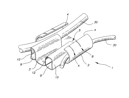
Figure 1 is a perspective view of the top part of the
connector assembly showing the first C-shaped element, the
electric cable and the second wedge type element being
wedged in to form the connector assembly.
Figure 2 is a perspective view of the bottom part of
the connector assembly which also shows the wedge type
element being inserted in the C shaped element.
15774 CA

2~.~4158
.:,
Figure 3 is a perspective view showing the C-shaped
member of the connector.
Figure 4 is a perspective view showing a sectioned
portion of the C-shaped member Figure 3 taken along line
4-4 of Figure 3.
Figure 5 is a frontal perspective view showing the
present invention in an assembled state.
Figure 6 is a perspective view of the assembled
connector, showing the cables arranged in the ocnnector
assembly.
Referring to Figures 1-2, one can determine the
connector assembly 1 comprised of a first C-shaped outer

21341~~
- 4 -
7 of C-shaped element 2 to clamp the cables 30 in the
connector assembly.
With the wedge type connectors a great variety of
combinations of conductor cable are made possible, being
limited solely to the sum of the minimum and maximum
conductor combinations, varying in accordance with a
specific cable diameter for each type of conductor.
The present invention has the purpose of providing an
alternative arrangement to the known connectors, which
will permit the technician to determine which is the
correct type of connector for an as yet unknown
arrangement in conductor cables, without damaging the
connectors (as it will not be necessary to assemble them
beforehand) .
It is possible to determine the type of connector
without previously assembling the connectors by the
incorporation of marks, preferably two already pre-
determined ones, in the C-shaped element 2, in the wedge
type element 3, or in both of them.
The marks may be made in the first and second
elements of the connectors during their manufacture or
later, and they may be superficial marks such as obtained
by painting, center punching, or any other means.
As is shown in Figures 1 and 2, the position of mark
A indicates the limit of acceptance of the connector in
accordance with the maximum sum of combinations of the
cable diameters. The position of mark "B" indicates the
15774 CA


l_ \
2134158
limit of acceptance of the minimum sum of the combination
of cables.
With marks A and B it is possible for the technician
to check, before applying the connector, whether the type
of connector chosen is correct, without risk of utilizing
an unsuitable connector.
As a practical example it may be cited that, as seen
from Figure 1, the fact that the frontal part of the wedge
is situated between marks A and B indicates that the sum
of the diameters of the conductor cables is within the
specific maximum and minimum limits for this type of
connector. Marks A and B are foreseen on both free edges
4 of the first C-shaped element 2.
As mentioned previously, marks A and B may
alternatively be made in the second wedge type element 3
(see Figure 2) for the purpose of aiding the installer to
visualize the assembly of the connector when seen from the
other side of same.
In a second embodiment, as shown in Figure 2, the
rear part of the C-shaped element 2 is placed between ,....
marks A and B, which indicates that the sum of the
diameters of the conductor cables is within a specific
minimum and maximum limit for the chosen connector.
Another embodiment of the present invention is shown
in Figures 3-6, Connector 1' comprises two pieces which
fit together to secure conductor cables 30' between them.
15774 CA


2134~.~8
- 6 -
One of the pieces is a member 2' of generally C-form which
is stamped and formed from a sheet, usually from sheet
metal, which is bent in the shape of a "C'°. In the bottom
portion 3' is provided a ramp 4' adjacent to an opening
5'.
Receptacle 2' has at least two radially arranged
recesses 7' forming inwardly directed channels 8 and
outwardly directed protuberances 9'.
The inner portion of receptacle 2' is provided with
a plurality of holding teeth 10' which are longitudinally
spaced apart along the length of the receptacle 2'.
The holding teeth 10' are preferably provided, in the
inner side wall 11' of receptacle 2', in the concave
portion of the same, are in the shape of notches, which
shape is suitable to increase the tensile strength of the
cables in the connector. In the embodiment of the present
invention, the notches have a diamond shape. It should be
noted that the diamond shape is an illustrative shape and
not a restrictive one.
Teeth 10' can be arranged in a way to be inserted
between the two recesses 7' in order to provide a greater
tensile strength to the receptacle 2' to better distribute
the tension of the connection along the cables and to
permit an increase of the tensile value of the cables in
the connector assembly.
The other piece of the connector assembly 1' is a
wedgeshaped member 12' comprised of a sheet material,
15774 CA


:..,
213~15~
preferably of sheet metal which is folded inwardly forming
two cylindrical portions 13' and 14', having channels 15'
and 16', respectively, which will secure and tense up
cables 30' against the wall 11' of receptacle 2'.
Usually, the receptacle 2 of the connector 1' is

Dessin représentatif
Une figure unique qui représente un dessin illustrant l'invention.
États administratifs

Pour une meilleure compréhension de l'état de la demande ou brevet qui figure sur cette page, la rubrique Mise en garde , et les descriptions de Brevet , États administratifs , Taxes périodiques et Historique des paiements devraient être consultées.

États administratifs

Titre Date
Date de délivrance prévu 2000-07-04
(22) Dépôt 1994-10-24
(41) Mise à la disponibilité du public 1995-05-17
Requête d'examen 1996-10-10
(45) Délivré 2000-07-04
Expiré 2014-10-24

Historique d'abandonnement

Il n'y a pas d'historique d'abandonnement

Historique des paiements

Type de taxes Anniversaire Échéance Montant payé Date payée
Le dépôt d'une demande de brevet 0,00 $ 1994-10-24
Enregistrement de documents 0,00 $ 1995-05-04
Taxe de maintien en état - Demande - nouvelle loi 2 1996-10-24 100,00 $ 1996-08-28
Requête d'examen 400,00 $ 1996-10-10
Taxe de maintien en état - Demande - nouvelle loi 3 1997-10-24 100,00 $ 1997-09-19
Taxe de maintien en état - Demande - nouvelle loi 4 1998-10-26 100,00 $ 1998-09-24
Taxe de maintien en état - Demande - nouvelle loi 5 1999-10-25 150,00 $ 1999-09-21
Taxe finale 300,00 $ 2000-04-05
Taxe de maintien en état - brevet - nouvelle loi 6 2000-10-24 150,00 $ 2000-09-20
Taxe de maintien en état - brevet - nouvelle loi 7 2001-10-24 150,00 $ 2001-09-19
Taxe de maintien en état - brevet - nouvelle loi 8 2002-10-24 150,00 $ 2002-09-18
Taxe de maintien en état - brevet - nouvelle loi 9 2003-10-24 150,00 $ 2003-09-17
Taxe de maintien en état - brevet - nouvelle loi 10 2004-10-25 250,00 $ 2004-09-16
Taxe de maintien en état - brevet - nouvelle loi 11 2005-10-24 250,00 $ 2005-10-04
Taxe de maintien en état - brevet - nouvelle loi 12 2006-10-24 250,00 $ 2006-10-02
Taxe de maintien en état - brevet - nouvelle loi 13 2007-10-24 250,00 $ 2007-10-01
Taxe de maintien en état - brevet - nouvelle loi 14 2008-10-24 250,00 $ 2008-09-30
Taxe de maintien en état - brevet - nouvelle loi 15 2009-10-26 450,00 $ 2009-10-01
Taxe de maintien en état - brevet - nouvelle loi 16 2010-10-25 450,00 $ 2010-09-30
Taxe de maintien en état - brevet - nouvelle loi 17 2011-10-24 450,00 $ 2011-09-30
Taxe de maintien en état - brevet - nouvelle loi 18 2012-10-24 450,00 $ 2012-10-01
Taxe de maintien en état - brevet - nouvelle loi 19 2013-10-24 450,00 $ 2013-09-30
Titulaires au dossier

Les titulaires actuels et antérieures au dossier sont affichés en ordre alphabétique.

Titulaires actuels au dossier
THE WHITAKER CORPORATION
Titulaires antérieures au dossier
DINIZ, MILTON EGAS
SORIANO, ALEXANDRE MARTINEZ
Les propriétaires antérieurs qui ne figurent pas dans la liste des « Propriétaires au dossier » apparaîtront dans d'autres documents au dossier.
Documents

Pour visionner les fichiers sélectionnés, entrer le code reCAPTCHA :


Pour visualiser une image, cliquer sur un lien dans la colonne description du document. Pour télécharger l'image (les images), cliquer l'une ou plusieurs cases à cocher dans la première colonne et ensuite cliquer sur le bouton "Télécharger sélection en format PDF (archive Zip)" ou le bouton "Télécharger sélection (en un fichier PDF fusionné)".

Liste des documents de brevet publiés et non publiés sur la BDBC .

Si vous avez des difficultés à accéder au contenu, veuillez communiquer avec le Centre de services à la clientèle au 1-866-997-1936, ou envoyer un courriel au Centre de service à la clientèle de l'OPIC.


Description du
Document 
Date
(yyyy-mm-dd) 
Nombre de pages   Taille de l'image (Ko) 
Abrégé 1995-10-22 1 56
Revendications 1995-10-22 1 62
Page couverture 2000-06-19 1 33
Dessins 1995-10-22 4 232
Description 1995-10-22 7 439
Page couverture 1995-10-22 1 50
Dessins représentatifs 2000-06-19 1 11
Cession 1994-10-24 8 280
Poursuite-Amendment 1996-10-10 2 88
Correspondance 1994-12-14 2 62
Correspondance 2000-04-05 1 36
Taxes 1996-08-28 1 55