Language selection

Search

Patent 2140871 Summary

Third-party information liability

Some of the information on this Web page has been provided by external sources. The Government of Canada is not responsible for the accuracy, reliability or currency of the information supplied by external sources. Users wishing to rely upon this information should consult directly with the source of the information. Content provided by external sources is not subject to official languages, privacy and accessibility requirements.

Claims and Abstract availability

Any discrepancies in the text and image of the Claims and Abstract are due to differing posting times. Text of the Claims and Abstract are posted:

  • At the time the application is open to public inspection;
  • At the time of issue of the patent (grant).
(12) Patent Application: (11) CA 2140871
(54) English Title: IDENTIFICATION DEVICE
(54) French Title: DISPOSITIF DE RECONNAISSANCE
Status: Dead
Bibliographic Data
(51) International Patent Classification (IPC):
  • H04B 1/59 (2006.01)
  • G01S 13/75 (2006.01)
  • G01S 13/78 (2006.01)
(72) Inventors :
  • KIRKNES, STEFFEN (Norway)
(73) Owners :
  • Q-FREE ASA (Norway)
(71) Applicants :
(74) Agent: SIM & MCBURNEY
(74) Associate agent:
(45) Issued:
(86) PCT Filing Date: 1993-06-30
(87) Open to Public Inspection: 1994-02-17
Examination requested: 2001-01-05
Availability of licence: N/A
(25) Language of filing: English

Patent Cooperation Treaty (PCT): Yes
(86) PCT Filing Number: PCT/NO1993/000103
(87) International Publication Number: WO1994/003982
(85) National Entry: 1995-01-23

(30) Application Priority Data:
Application No. Country/Territory Date
923022 Norway 1992-07-31

Abstracts

English Abstract


Method and device for individual identification using electronic interrogation by transmission and reception of signals of a
certain frequency from a transmitter/receiver unit. The device comprises an identification chip (1), comprising an inactive code
carrier (2), such as a SAW-component, and an antenna (4), where the antenna (4) receives the transmitted signal which then is ap-
plied to the code carrier (2), and a signal, superimposed with the individual code of the code carrier, is reflected from the code
carrier (2). Two signals (f0, f1) of different frequencies are mixed after reception by the antenna (4), and are applied to the
code carrier (2), which reflects a coded signal (f2'). This coded signal (f2') is mixed with the first transmitted signal (f0) to
provide a second coded signal (f1'), having a frequency corresponding to the frequency of the second transmitted signal (f1).


Claims

Note: Claims are shown in the official language in which they were submitted.


Claims:
1. Method for individual identification using electronic interrogation by transmis-
sion and reception of signals of a certain frequancy from a transmitter/receiver unit,
wherein an identification chip (1), comprising a inactive code carrier (2), such as a
SAW-component, and an antenna (4), where the antenna (4) receives the transmitted
signal which then is applied to the code carrier (2), and a signal, superimposed with
the individual code of the code carrier, is reflected from the code carrier (2),characterized by comprising the following steps:
transmission, from the transmitter/receiver unit, of a first and a second signal(f0, f1) of different frequencies,
mixing the two signals (f0, f1) after reception thereof by the antenna (4), to provide
a third signal (f2), having a frequency which is a combination of the frequencies of
the first and the second signals (f0, f1),
applying the third signal (f2) to the code carrier (2), so that the code carrier ref-
lects a first coded signal (f2.) having a frequency corresponding to the frequency of
the third signal (f2),
mixing the first coded signal (f2') with the first transmitted signal (f0) resulting in a
second coded signal (f1'), having a frequency corresponding to the frequency of the
second transmitted signal (f1), and
reflecting the second coded signal (f1') to the transmitter/receiver unit.
2. Identification chip for individual identification using electronical interrogation
by transmission and reception of a signal from a transmitter/receiver unit, having a
certain frequency, where the identification chip (1) comprises an inactive code
carrier (2), such as a SAW-component, and an antenna (4), where the antenna (4) is
provided for receiving the transmitted signal, which then is applied to the codecarrier (2), and the code carrier (2) provides a reflected signal superimposed with the
individual the code of code carrier (2), characterized by
the antenna (4) being provided to receive two signals (f0, f1) having different
frequencies.
a mixer (3), provided for mixing the two signals (f0, f1) resulting in a third signal
(f2) having a frequency which is the combined frequencies of the first and the second
signals (f0, f1),


a signal path (6, 7) provided for applying the mixed signal (f2) to the code carrier
(2), for the provision of a reflected, coded signal (f2') from the code carrier, wherein
the signal path (6, 7) applies the reflected, coded signal (f2') to the mixer (3), and
the mixer is further provided for mixing the reflected, coded signal (f2') with one
of the transmitted signals (f0) for the provision of a second coded signal (f1') having a
frequency corresponding to the second transmitted signal (f1), and which is supplied
to the antenna (4) for reflection to the transmitter/receiver unit.
3. Identification chip according to claim 2,
characterized by the signal path (6, 7) comprising a transducer (7).
4. Identification chip according to claim 2 or 3,
characterized by the mixer (3) comprising a diode (5).
5. Identification chip according to claim 2 or 3,
characterized by the mixer (3) comprising a plurality of diodes (5).
6. Identification chip according to any one of claims 2-5,
characterized by the signal path (6, 7) further comprising a inactive network (6) for
impedance matching.
7. Identification chip according to any one of claims 2-6,
characterized by the antenna (4) comprising a plurality of aperture connected micro
strip antennas.
8. Identification chip according to any one of claims 2-6,
characterized by the code carrier (2) being a SAW (Surface Acoustic Wave) -
component.
9. Identification chip according to any one of claims 2-6,
characterized by the code carrier (2) being a BAW (Bulk Acoustic Wave) -
component.
10. Identification chip according to any one of claims 2-6,
characterized by the code carrier (2) comprising a frequency source.

Description

Note: Descriptions are shown in the official language in which they were submitted.


W O 94/03982 2 ~ A ~ 8 7 1. PC~r/N 093/00103
IDENTIFICATION DEVICE.

The present invention concerns a method for individual idçntific~tion using
electronic int~llùgalion, and an identific~tion chip for this purpose, according to the
introductory part of patent claim 1, resp. 2.
The invention is based upon an idçntifi~tion chip having an inactive code carrier,
S which typically compricPs a so-called SAW (Surface Acoustic Wave) - col"pollent.
Such SAW-cclllpollents are well known for individual idçntifi~ti~n. The SAW-
cclllponent is coded, so that each chip has its own code, which gives a unique
itlçntific~tion of the chip, and the object to which it is f~ctenPd In ~ ition, each
chip contains an ~ntPnn~, and optionally col"ponenls for i.,.~l~nce m~tt~hing and
10 physical enr~psul~tion.
The use of such in-içntific~tic)n chips is based upon a central unit compricing a
tr~ncmittP and a receiver, ge~ g a microwave signal, which is tr~ncmittPA and
received by the ~nlPnll~ on the idçntific~tion chip. The signal is then converted to an
acoustic surface wave, which propagates along the SAW-col,lponent, and g*es
15 reflectionc, ~ luling the code of this cc",ponent. These reflçctPA signals are then
converted to an electronic signal. This signal is tr~ncmittçd from the chip and is
received by the receiver in the central unit, where it is further p~ocessed for
dermining the individual idçntifi~tion.
There are many dirr~,ei t embo-limPntc of these co",ponents in respect of code
20 m~th~lc, code length, physical geometry, choice of m~tçri~l, etc. Furthermore, it is
also known to use so-called BAW (Bulk Acoustic Wave) - co",pone"L~ for similar
purposes.
A disadvantage with SAW-chips is that they are relatively narrow-b~nded, so thateach kind of chip must be manufactured with a special geometry. This makes it more
25 difficult to provide efficient utili7~tion of frequencies above 1 GHz.
It is therefore an object of the present invention to provide a method and a device
for individual identification using electronic illl~.~ugation of the above mentioned
kind which permits a more flexible use of frequenciçs
The object of the invention is achieved with a method having rea~ures as stated in
30 the chara -tçri7ing part of patent claim 1 and an identification chip for use in
connection with the invention is stated in the char~ct~ri7ing part of patent claim 2.
Further fealules in the device are stated in the dependent claims.

W O 94/03982 - ` ~ Z~40~1. PC~r/N 093/00103


In the following, a prcrcllcd embodiment of the invention will be described withreference to the accol-lpanying drawings, in which:
Fig. 1 is a block diagram of a device for use according to present invention,
Fig. 2a and 2b are frequency diagrams for signals tr~ncmitt~d from the
5 tr~ncmitter/receiver unit,
Fig. 3a and 3b are frequency diagrams for refl~cted, coded signal, and
Fig. 4 is a more det~iled drawing of the col."~onents which are parts in a device
according to present invention.
Fig. 1 shows an identification chip according to present invention. The identifica-
10 tion chip is generally denoted 1, and comprises a code carrier 2, e.g. a SAW-com-
ponent, a frequency mixer 3, and an antenna 4. Signals from a tr~ncmittPr (not
shown) are received by the ~ntenna 4 and are propagated via the mixer 3, to the code
carrier 2. From the code carrier 2 a signal is reflected via the mixer 3 and trans-
mitted to the ~ t~llnA 4, and back to tr~ncmitterlreceiver unit (not shown).
15 Fig. 2a is a frequency diagram illustrating the signal which is tr~ncmitted from the
tr~ncmitt~r. In this example of an embodiment, an intcllogation signal f, is trans-
mitted together with a carrier signal fO. This signal is received by the ~ntenn~ 4 in
the identifc~tion chip 1. In the mixer 3, a mixed signal f2, shown in Fig. 2b, is
eYtraçted and taken to the code carrier 2. The signal f2 preferably has a frequency
20 which is the frequency dirrclcnce of the signals fi and fO.
Fig. 3a shows the refle~ted signal f2. from the code carrier 2. This signal f2 has
superimposed thereon the indiviual code carrier 2. Signal f2. is then again mixed, so
that an identification coded mixing signal denoted f, is formed, as shown in Fig. 3b.
As a result the tr~ncmitted and received signals fO, fi; fO, fl., have a much higher fre-
25 quency than the signals f2; f2 which are used internally in the indentific~tion chip 1.
In Fig. 4 is shown a specific embodiment of present invention. An identificationchip 1 comprises a SAW-colll~Jonent 2 of per se known kind. The ~ntenn~ 4 is an
aperture-connected microstrip ~ntenn~ Furthermore, the mixer 3 from Fig. 1
comprises a diode 5. The antenna 4 is connected to a tr~ncducçr 7 via an impedence
30 match 6. The tr~ncducer 7 converts the electronic signal to and from a surface
acoustic wave. The antenna 4 receives signals with frequencies fi and fO. These
signals are mixed by a diode 5, so that a mixed difference signal is transferred to the

WO 94/03982 i~l40871. PCI/NO93/00103


tr~nsducer 7 and is converted to a surface acuostic wave for the code carrier 2.In a further embodiment the mixing signal can come from a frequency source
which is internal of the identification chip.
It is also possible to use this technology with other kinds of code carriers, such as
S BAW (Bulk Acoustic Wave).
The mixer 3 may constitute more than one diode, or be acheived in other ways
which are known to the person skilled in the art.
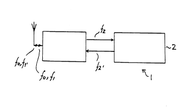
Representative Drawing
A single figure which represents the drawing illustrating the invention.
Administrative Status

For a clearer understanding of the status of the application/patent presented on this page, the site Disclaimer , as well as the definitions for Patent , Administrative Status , Maintenance Fee  and Payment History  should be consulted.

Administrative Status

Title Date
Forecasted Issue Date Unavailable
(86) PCT Filing Date 1993-06-30
(87) PCT Publication Date 1994-02-17
(85) National Entry 1995-01-23
Examination Requested 2001-01-05
Dead Application 2006-06-30

Abandonment History

Abandonment Date Reason Reinstatement Date
2000-06-30 FAILURE TO REQUEST EXAMINATION 2001-01-05
2000-06-30 FAILURE TO PAY APPLICATION MAINTENANCE FEE 2001-01-04
2005-06-30 FAILURE TO PAY APPLICATION MAINTENANCE FEE

Payment History

Fee Type Anniversary Year Due Date Amount Paid Paid Date
Application Fee $0.00 1995-01-23
Maintenance Fee - Application - New Act 2 1995-06-30 $50.00 1995-01-23
Registration of a document - section 124 $0.00 1995-07-27
Maintenance Fee - Application - New Act 3 1996-07-01 $50.00 1996-06-26
Maintenance Fee - Application - New Act 4 1997-06-30 $50.00 1997-05-09
Maintenance Fee - Application - New Act 5 1998-06-30 $150.00 1998-06-26
Registration of a document - section 124 $100.00 1999-06-02
Maintenance Fee - Application - New Act 6 1999-06-30 $150.00 1999-06-04
Reinstatement: Failure to Pay Application Maintenance Fees $200.00 2001-01-04
Maintenance Fee - Application - New Act 7 2000-06-30 $150.00 2001-01-04
Reinstatement - failure to request examination $200.00 2001-01-05
Request for Examination $400.00 2001-01-05
Maintenance Fee - Application - New Act 8 2001-07-03 $150.00 2001-06-08
Maintenance Fee - Application - New Act 9 2002-07-01 $150.00 2002-06-13
Maintenance Fee - Application - New Act 10 2003-06-30 $200.00 2003-06-10
Maintenance Fee - Application - New Act 11 2004-06-30 $250.00 2004-06-22
Owners on Record

Note: Records showing the ownership history in alphabetical order.

Current Owners on Record
Q-FREE ASA
Past Owners on Record
KIRKNES, STEFFEN
MICRO DESIGN AS
Past Owners that do not appear in the "Owners on Record" listing will appear in other documentation within the application.
Documents

To view selected files, please enter reCAPTCHA code :


To view images, click a link in the Document Description column. To download the documents, select one or more checkboxes in the first column and then click the "Download Selected in PDF format (Zip Archive)" or the "Download Selected as Single PDF" button.

List of published and non-published patent-specific documents on the CPD .

If you have any difficulty accessing content, you can call the Client Service Centre at 1-866-997-1936 or send them an e-mail at CIPO Client Service Centre.


Document
Description 
Date
(yyyy-mm-dd) 
Number of pages   Size of Image (KB) 
Representative Drawing 1997-06-18 1 2
Cover Page 1995-08-23 1 15
Abstract 1994-02-17 1 43
Description 1994-02-17 3 122
Claims 1994-02-17 2 88
Drawings 1994-02-17 1 10
Claims 2004-01-21 3 91
Description 2004-01-21 5 190
Prosecution-Amendment 2004-01-21 8 282
Fees 1998-06-26 1 58
Assignment 1995-01-23 13 511
PCT 1995-01-23 14 564
Correspondence 1999-08-03 1 37
Prosecution-Amendment 2001-01-05 1 64
Prosecution-Amendment 2003-07-21 2 37
Fees 2003-06-10 1 49
Fees 2001-06-08 1 49
Fees 2001-01-04 1 61
Fees 2002-06-13 1 50
Fees 2004-06-22 1 52
Fees 1997-05-09 1 57
Fees 1996-06-26 1 49
Fees 1995-01-23 1 74