Sélection de la langue

Search

Sommaire du brevet 2140871 

Énoncé de désistement de responsabilité concernant l'information provenant de tiers

Une partie des informations de ce site Web a été fournie par des sources externes. Le gouvernement du Canada n'assume aucune responsabilité concernant la précision, l'actualité ou la fiabilité des informations fournies par les sources externes. Les utilisateurs qui désirent employer cette information devraient consulter directement la source des informations. Le contenu fourni par les sources externes n'est pas assujetti aux exigences sur les langues officielles, la protection des renseignements personnels et l'accessibilité.

Disponibilité de l'Abrégé et des Revendications

L'apparition de différences dans le texte et l'image des Revendications et de l'Abrégé dépend du moment auquel le document est publié. Les textes des Revendications et de l'Abrégé sont affichés :

  • lorsque la demande peut être examinée par le public;
  • lorsque le brevet est émis (délivrance).
(12) Demande de brevet: (11) CA 2140871
(54) Titre français: DISPOSITIF DE RECONNAISSANCE
(54) Titre anglais: IDENTIFICATION DEVICE
Statut: Morte
Données bibliographiques
Abrégés

Abrégé anglais


Method and device for individual identification using electronic interrogation by transmission and reception of signals of a
certain frequency from a transmitter/receiver unit. The device comprises an identification chip (1), comprising an inactive code
carrier (2), such as a SAW-component, and an antenna (4), where the antenna (4) receives the transmitted signal which then is ap-
plied to the code carrier (2), and a signal, superimposed with the individual code of the code carrier, is reflected from the code
carrier (2). Two signals (f0, f1) of different frequencies are mixed after reception by the antenna (4), and are applied to the
code carrier (2), which reflects a coded signal (f2'). This coded signal (f2') is mixed with the first transmitted signal (f0) to
provide a second coded signal (f1'), having a frequency corresponding to the frequency of the second transmitted signal (f1).

Revendications

Note : Les revendications sont présentées dans la langue officielle dans laquelle elles ont été soumises.


Claims:
1. Method for individual identification using electronic interrogation by transmis-
sion and reception of signals of a certain frequancy from a transmitter/receiver unit,
wherein an identification chip (1), comprising a inactive code carrier (2), such as a
SAW-component, and an antenna (4), where the antenna (4) receives the transmitted
signal which then is applied to the code carrier (2), and a signal, superimposed with
the individual code of the code carrier, is reflected from the code carrier (2),characterized by comprising the following steps:
transmission, from the transmitter/receiver unit, of a first and a second signal(f0, f1) of different frequencies,
mixing the two signals (f0, f1) after reception thereof by the antenna (4), to provide
a third signal (f2), having a frequency which is a combination of the frequencies of
the first and the second signals (f0, f1),
applying the third signal (f2) to the code carrier (2), so that the code carrier ref-
lects a first coded signal (f2.) having a frequency corresponding to the frequency of
the third signal (f2),
mixing the first coded signal (f2') with the first transmitted signal (f0) resulting in a
second coded signal (f1'), having a frequency corresponding to the frequency of the
second transmitted signal (f1), and
reflecting the second coded signal (f1') to the transmitter/receiver unit.
2. Identification chip for individual identification using electronical interrogation
by transmission and reception of a signal from a transmitter/receiver unit, having a
certain frequency, where the identification chip (1) comprises an inactive code
carrier (2), such as a SAW-component, and an antenna (4), where the antenna (4) is
provided for receiving the transmitted signal, which then is applied to the codecarrier (2), and the code carrier (2) provides a reflected signal superimposed with the
individual the code of code carrier (2), characterized by
the antenna (4) being provided to receive two signals (f0, f1) having different
frequencies.
a mixer (3), provided for mixing the two signals (f0, f1) resulting in a third signal
(f2) having a frequency which is the combined frequencies of the first and the second
signals (f0, f1),


a signal path (6, 7) provided for applying the mixed signal (f2) to the code carrier
(2), for the provision of a reflected, coded signal (f2') from the code carrier, wherein
the signal path (6, 7) applies the reflected, coded signal (f2') to the mixer (3), and
the mixer is further provided for mixing the reflected, coded signal (f2') with one
of the transmitted signals (f0) for the provision of a second coded signal (f1') having a
frequency corresponding to the second transmitted signal (f1), and which is supplied
to the antenna (4) for reflection to the transmitter/receiver unit.
3. Identification chip according to claim 2,
characterized by the signal path (6, 7) comprising a transducer (7).
4. Identification chip according to claim 2 or 3,
characterized by the mixer (3) comprising a diode (5).
5. Identification chip according to claim 2 or 3,
characterized by the mixer (3) comprising a plurality of diodes (5).
6. Identification chip according to any one of claims 2-5,
characterized by the signal path (6, 7) further comprising a inactive network (6) for
impedance matching.
7. Identification chip according to any one of claims 2-6,
characterized by the antenna (4) comprising a plurality of aperture connected micro
strip antennas.
8. Identification chip according to any one of claims 2-6,
characterized by the code carrier (2) being a SAW (Surface Acoustic Wave) -
component.
9. Identification chip according to any one of claims 2-6,
characterized by the code carrier (2) being a BAW (Bulk Acoustic Wave) -
component.
10. Identification chip according to any one of claims 2-6,
characterized by the code carrier (2) comprising a frequency source.
Description

Note : Les descriptions sont présentées dans la langue officielle dans laquelle elles ont été soumises.


W O 94/03982 2 ~ A ~ 8 7 1. PC~r/N 093/00103
IDENTIFICATION DEVICE.

The present invention concerns a method for individual idçntific~tion using
electronic int~llùgalion, and an identific~tion chip for this purpose, according to the
introductory part of patent claim 1, resp. 2.
The invention is based upon an idçntifi~tion chip having an inactive code carrier,
S which typically compricPs a so-called SAW (Surface Acoustic Wave) - col"pollent.
Such SAW-cclllpollents are well known for individual idçntifi~ti~n. The SAW-
cclllponent is coded, so that each chip has its own code, which gives a unique
itlçntific~tion of the chip, and the object to which it is f~ctenPd In ~ ition, each
chip contains an ~ntPnn~, and optionally col"ponenls for i.,.~l~nce m~tt~hing and
10 physical enr~psul~tion.
The use of such in-içntific~tic)n chips is based upon a central unit compricing a
tr~ncmittP and a receiver, ge~ g a microwave signal, which is tr~ncmittPA and
received by the ~nlPnll~ on the idçntific~tion chip. The signal is then converted to an
acoustic surface wave, which propagates along the SAW-col,lponent, and g*es
15 reflectionc, ~ luling the code of this cc",ponent. These reflçctPA signals are then
converted to an electronic signal. This signal is tr~ncmittçd from the chip and is
received by the receiver in the central unit, where it is further p~ocessed for
dermining the individual idçntifi~tion.
There are many dirr~,ei t embo-limPntc of these co",ponents in respect of code
20 m~th~lc, code length, physical geometry, choice of m~tçri~l, etc. Furthermore, it is
also known to use so-called BAW (Bulk Acoustic Wave) - co",pone"L~ for similar
purposes.
A disadvantage with SAW-chips is that they are relatively narrow-b~nded, so thateach kind of chip must be manufactured with a special geometry. This makes it more
25 difficult to provide efficient utili7~tion of frequencies above 1 GHz.
It is therefore an object of the present invention to provide a method and a device
for individual identification using electronic illl~.~ugation of the above mentioned
kind which permits a more flexible use of frequenciçs
The object of the invention is achieved with a method having rea~ures as stated in
30 the chara -tçri7ing part of patent claim 1 and an identification chip for use in
connection with the invention is stated in the char~ct~ri7ing part of patent claim 2.
Further fealules in the device are stated in the dependent claims.

W O 94/03982 - ` ~ Z~40~1. PC~r/N 093/00103


In the following, a prcrcllcd embodiment of the invention will be described withreference to the accol-lpanying drawings, in which:
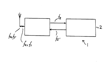
Fig. 1 is a block diagram of a device for use according to present invention,
Fig. 2a and 2b are frequency diagrams for signals tr~ncmitt~d from the
5 tr~ncmitter/receiver unit,
Fig. 3a and 3b are frequency diagrams for refl~cted, coded signal, and
Fig. 4 is a more det~iled drawing of the col."~onents which are parts in a device
according to present invention.
Fig. 1 shows an identification chip according to present invention. The identifica-
10 tion chip is generally denoted 1, and comprises a code carrier 2, e.g. a SAW-com-
ponent, a frequency mixer 3, and an antenna 4. Signals from a tr~ncmittPr (not
shown) are received by the ~ntenna 4 and are propagated via the mixer 3, to the code
carrier 2. From the code carrier 2 a signal is reflected via the mixer 3 and trans-
mitted to the ~ t~llnA 4, and back to tr~ncmitterlreceiver unit (not shown).
15 Fig. 2a is a frequency diagram illustrating the signal which is tr~ncmitted from the
tr~ncmitt~r. In this example of an embodiment, an intcllogation signal f, is trans-
mitted together with a carrier signal fO. This signal is received by the ~ntenn~ 4 in
the identifc~tion chip 1. In the mixer 3, a mixed signal f2, shown in Fig. 2b, is
eYtraçted and taken to the code carrier 2. The signal f2 preferably has a frequency
20 which is the frequency dirrclcnce of the signals fi and fO.
Fig. 3a shows the refle~ted signal f2. from the code carrier 2. This signal f2 has
superimposed thereon the indiviual code carrier 2. Signal f2. is then again mixed, so
that an identification coded mixing signal denoted f, is formed, as shown in Fig. 3b.
As a result the tr~ncmitted and received signals fO, fi; fO, fl., have a much higher fre-
25 quency than the signals f2; f2 which are used internally in the indentific~tion chip 1.
In Fig. 4 is shown a specific embodiment of present invention. An identificationchip 1 comprises a SAW-colll~Jonent 2 of per se known kind. The ~ntenn~ 4 is an
aperture-connected microstrip ~ntenn~ Furthermore, the mixer 3 from Fig. 1
comprises a diode 5. The antenna 4 is connected to a tr~ncducçr 7 via an impedence
30 match 6. The tr~ncducer 7 converts the electronic signal to and from a surface
acoustic wave. The antenna 4 receives signals with frequencies fi and fO. These
signals are mixed by a diode 5, so that a mixed difference signal is transferred to the

WO 94/03982 i~l40871. PCI/NO93/00103


tr~nsducer 7 and is converted to a surface acuostic wave for the code carrier 2.In a further embodiment the mixing signal can come from a frequency source
which is internal of the identification chip.
It is also possible to use this technology with other kinds of code carriers, such as
S BAW (Bulk Acoustic Wave).
The mixer 3 may constitute more than one diode, or be acheived in other ways
which are known to the person skilled in the art.

Dessin représentatif
Une figure unique qui représente un dessin illustrant l'invention.
États administratifs

Pour une meilleure compréhension de l'état de la demande ou brevet qui figure sur cette page, la rubrique Mise en garde , et les descriptions de Brevet , États administratifs , Taxes périodiques et Historique des paiements devraient être consultées.

États administratifs

Titre Date
Date de délivrance prévu Non disponible
(86) Date de dépôt PCT 1993-06-30
(87) Date de publication PCT 1994-02-17
(85) Entrée nationale 1995-01-23
Requête d'examen 2001-01-05
Demande morte 2006-06-30

Historique d'abandonnement

Date d'abandonnement Raison Reinstatement Date
2000-06-30 Absence de requête d'examen 2001-01-05
2000-06-30 Taxe périodique sur la demande impayée 2001-01-04
2005-06-30 Taxe périodique sur la demande impayée

Historique des paiements

Type de taxes Anniversaire Échéance Montant payé Date payée
Le dépôt d'une demande de brevet 0,00 $ 1995-01-23
Taxe de maintien en état - Demande - nouvelle loi 2 1995-06-30 50,00 $ 1995-01-23
Enregistrement de documents 0,00 $ 1995-07-27
Taxe de maintien en état - Demande - nouvelle loi 3 1996-07-01 50,00 $ 1996-06-26
Taxe de maintien en état - Demande - nouvelle loi 4 1997-06-30 50,00 $ 1997-05-09
Taxe de maintien en état - Demande - nouvelle loi 5 1998-06-30 150,00 $ 1998-06-26
Enregistrement de documents 100,00 $ 1999-06-02
Taxe de maintien en état - Demande - nouvelle loi 6 1999-06-30 150,00 $ 1999-06-04
Rétablissement: taxe de maintien en état non-payées pour la demande 200,00 $ 2001-01-04
Taxe de maintien en état - Demande - nouvelle loi 7 2000-06-30 150,00 $ 2001-01-04
Rétablissement - absence de requête d'examen 200,00 $ 2001-01-05
Requête d'examen 400,00 $ 2001-01-05
Taxe de maintien en état - Demande - nouvelle loi 8 2001-07-03 150,00 $ 2001-06-08
Taxe de maintien en état - Demande - nouvelle loi 9 2002-07-01 150,00 $ 2002-06-13
Taxe de maintien en état - Demande - nouvelle loi 10 2003-06-30 200,00 $ 2003-06-10
Taxe de maintien en état - Demande - nouvelle loi 11 2004-06-30 250,00 $ 2004-06-22
Titulaires au dossier

Les titulaires actuels et antérieures au dossier sont affichés en ordre alphabétique.

Titulaires actuels au dossier
Q-FREE ASA
Titulaires antérieures au dossier
KIRKNES, STEFFEN
MICRO DESIGN AS
Les propriétaires antérieurs qui ne figurent pas dans la liste des « Propriétaires au dossier » apparaîtront dans d'autres documents au dossier.
Documents

Pour visionner les fichiers sélectionnés, entrer le code reCAPTCHA :


Pour visualiser une image, cliquer sur un lien dans la colonne description du document. Pour télécharger l'image (les images), cliquer l'une ou plusieurs cases à cocher dans la première colonne et ensuite cliquer sur le bouton "Télécharger sélection en format PDF (archive Zip)" ou le bouton "Télécharger sélection (en un fichier PDF fusionné)".

Liste des documents de brevet publiés et non publiés sur la BDBC .

Si vous avez des difficultés à accéder au contenu, veuillez communiquer avec le Centre de services à la clientèle au 1-866-997-1936, ou envoyer un courriel au Centre de service à la clientèle de l'OPIC.


Description du
Document 
Date
(yyyy-mm-dd) 
Nombre de pages   Taille de l'image (Ko) 
Dessins représentatifs 1997-06-18 1 2
Page couverture 1995-08-23 1 15
Abrégé 1994-02-17 1 43
Description 1994-02-17 3 122
Revendications 1994-02-17 2 88
Dessins 1994-02-17 1 10
Revendications 2004-01-21 3 91
Description 2004-01-21 5 190
Poursuite-Amendment 2004-01-21 8 282
Taxes 1998-06-26 1 58
Cession 1995-01-23 13 511
PCT 1995-01-23 14 564
Correspondance 1999-08-03 1 37
Poursuite-Amendment 2001-01-05 1 64
Poursuite-Amendment 2003-07-21 2 37
Taxes 2003-06-10 1 49
Taxes 2001-06-08 1 49
Taxes 2001-01-04 1 61
Taxes 2002-06-13 1 50
Taxes 2004-06-22 1 52
Taxes 1997-05-09 1 57
Taxes 1996-06-26 1 49
Taxes 1995-01-23 1 74