Language selection

Search

Patent 2146081 Summary

Third-party information liability

Some of the information on this Web page has been provided by external sources. The Government of Canada is not responsible for the accuracy, reliability or currency of the information supplied by external sources. Users wishing to rely upon this information should consult directly with the source of the information. Content provided by external sources is not subject to official languages, privacy and accessibility requirements.

Claims and Abstract availability

Any discrepancies in the text and image of the Claims and Abstract are due to differing posting times. Text of the Claims and Abstract are posted:

  • At the time the application is open to public inspection;
  • At the time of issue of the patent (grant).
(12) Patent: (11) CA 2146081
(54) English Title: THREADED VALVE WITH SAFETY JOINT
(54) French Title: ROBINET FILETE AVEC JOINT DE SECURITE
Status: Expired
Bibliographic Data
(51) International Patent Classification (IPC):
  • F16L 19/02 (2006.01)
  • F16B 39/02 (2006.01)
  • F16K 27/00 (2006.01)
  • F16L 15/00 (2006.01)
(72) Inventors :
  • SCARAMUCCI, JOHN P. (United States of America)
(73) Owners :
  • BALCOR HOLDING CORPORATION (United States of America)
(71) Applicants :
(74) Agent: RIDOUT & MAYBEE LLP
(74) Associate agent:
(45) Issued: 1998-08-04
(22) Filed Date: 1995-03-31
(41) Open to Public Inspection: 1995-12-04
Examination requested: 1995-03-31
Availability of licence: N/A
(25) Language of filing: English

Patent Cooperation Treaty (PCT): No

(30) Application Priority Data:
Application No. Country/Territory Date
08/254,024 United States of America 1994-06-03

Abstracts

English Abstract


A safety joint for a threaded fitting, such as a valve.
A deformable lip is formed on one end of the fitting around an
adapter threaded into the respective end of the fitting. The lip
is deformed against the wrench flats on the adapter to lock the
adapter to the fitting.


French Abstract

Joint de sûreté d'un raccord fileté, comme une vanne. Une lèvre déformable se trouve à une extrémité du raccord autour d'un adaptateur fileté dans l'extrémité correspondante du raccord. La lèvre est déformée par les méplats de la clé sur l'adaptateur pour bloquer ce dernier sur le raccord.

Claims

Note: Claims are shown in the official language in which they were submitted.

THE EMBODIMENTS OF THE INVENTION IN WHICH AN EXCLUSIVE
PROPERTY OR PRIVILEGE IS CLAIMED ARE DEFINED AS FOLLOWS:
1. The combination of:
a fitting having a body portion adapted to be
threaded onto the ends of adjacent pipe
sections;
an adapter threaded into one end of the fitting
body having at least a pair of wrench flats on
the outer surface thereof; and
a deformable lip on the body portion of the fitting
adjacent the adapter positioned to be deformed
against the wrench flats to lock the adapter
to the fitting.


2. The combination of claim 1 wherein the fitting is a
valve.


3. The combination of claim 1 wherein the wrench flats
on the adapter circumscribe the adapter.


4. The combination of claim 3 wherein the deformable
lip, before deformation, surrounds the portion of the adapter
adjacent the fitting body.


5.

5. The combination of:
a fitting having opposite ends, a threaded bore in
one end thereof and a counterbore therein
adjacent the threaded bore forming a
circumferential, deformable lip at said one
end;
an adapter having an externally threaded portion
threadedly engaging said threaded bore and a
head portion abutting said one end inside of
said lip;
whereby said lip may be deformed radially inwardly
against the outer periphery of the adapter.


6. The combination of claim 5 wherein the adapter has
wrench flats on the outer surface thereof positioned to be engaged
by the lip.


7. The combination of claim S wherein the fitting is a
valve.


8. The combination of claim 5 wherein the fitting has
a threaded bore in each end thereof.


9. In a fitting having opposite ends and an adapter
threaded into one end thereof, said adapter having wrench flats on
the outer surface thereof, the steps of:
forming a deformable lip on said one end of the
fitting around the adapter;
then deforming the lip against the wrench flats to
lock the adapter to the fitting.


10. The method of claim 9 wherein the fitting is a
valve.


Description

Note: Descriptions are shown in the official language in which they were submitted.


21~6081
-


PATENT
THREADED VALVE WITH SAFETY JOINT
Brief SummarY of the Invention
1. Field of the Invention
This invention relates generally to improvements in
safety joints for threaded fittings, and more particularly, but not
by way of limitation, to a safety joint for a threaded valve.
2. Backqround of the Invention
Valves and pipe fittings are often made with a threaded
body ~oint. This threaded body joint allows the installation of
all internal parts, such as the valve member and seats in a valve.
Sometimes, when threading the valve or other fitting on the pipe,
or when unthreading the pipe from one end of the valve or the
fitting, the body joint will accidentally unscrew. This causes the
valve to be disassembled. If the valve is under pressure or later
pressurized, it can blow up.
Many users are requiring this type of valve to have the
threaded body joint more positively retained. A common t~chn;que
to help prevent the problem is to tack weld the joint, drill and
pin after assembly, or to use a threaded adhesive. Each of these
solutions have inherent pro~lems, such as the loss of
repairability.
3. Summar~ of the Invention
The present invention secures the body joint of a fitting
or valve by providing a deformable lip as a part of the body joint
which is deformed against the wrench flats of the adapter forming

2146081

a part of the body joint, such that the adapter will be secured in
position against normal forces, but can be forcibly unthreaded if
necessary for repair of the valve or fitting.
Brief DescriPti~n of the Drawinqs
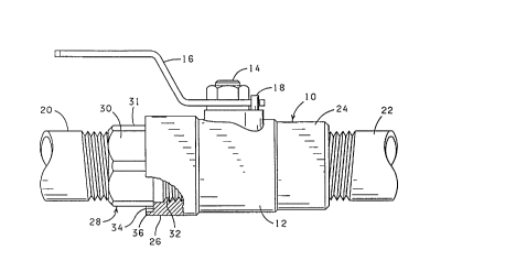
FIG. 1 is a side view of a valve constructed pursuant to
this invention, with a portion of the body joint being shown in
cross-section.
FIG. 2 is an end view of the body joint end of the valve
of FIG. 1 with the pipe at that end of the valve removed.
FIG. 3 is a view similar to FIG. 1 showing the body joint
portion, with the lip deformed against the adapter.
FIG. 4 is an end view of the structure as formed in FIG.
3 with the pipe removed.
DescriPtion of the Preferred ~mhodiment
Referring to the drawings in detail, and particularly
FIG. 1, reference character 10 generally designates a valve
constructed pursuant to this invention. The valve 10 comprises a
body 12 cont~;n;ng the usual valve member and seats (not shown),
with a valve stem 14 extending through the side wall of the body
12. A handle 16 is suitably secured on the valve stem 14 and is
employed for turning the valve stem 14, and hence the valve member
to open and close the valve. The valve 10 also normally includes
a stop pin 18 positioned to engage the handle 16 and control the
amount of turning of the valve stem 14.
The valve 10 is of the type for being threadedly
connected to adjacent pipe sections 20 and 22. Normally, the pipe

2146081
-


section 22 is threaded directly into the respective end 24 of the
valve body 12; whereas the pipe section 20 is connected to the
respective end 26 of the valve body 12 by means of an adapter 28.
The inner diameter of the end 26 of the valve body is larger than
the inner diameter of the end 24, such that the internal components
of the valve 10 can be installed through the end 26 and then held
in position with the adapter 28. The combination of the adapter 28
and the end 26 of the valve body 12 is normally referred to as a
"threaded body joint". It will also be observed that the adapter
10 28 is provided with a series of wrench flats 30 circumscribing the
head portion 31 of the adapter, by means of which the adapter 28
can be threaded into and from the body 12.
Pursuant to the present invention, the internally
threaded bore 3 2 at the end 26 of the body 12 is provided with a
counterbore 34, forming a lip 36 surrounding the adjacent head
portion 31 of the adapter 28. In other words, the adapter 28 is
sized to be threaded into the end 26 of the-body 12 until the head
portion 31 abuts the end of the counterbore 34. As shown in FIGS.
3 and 4, the lip 36 is of such a size that it can be deformed
radially inwardly to engage the wrench flats 30 of the adapter 28.
With this arrangement, the adapter 28 will be secured in the valve
body 12 against normal unthreading forces. ~owever, if access to
the inside of the valve 10 is required, what may be considered an
excessive force can be applied to unthread the adapter 28 and at
least partially deform the lip 36 back out toward the position
shown in FIG. 1. When the lip 36 is deformed inwardly as shown in


21~6081

FIGS. 3 and 4, the valve 10 may be unthreaded from the pipe section
22, for example, for whatever -'-eason, and the adapter 28 will be
maintained in secure connection with the valve-body. For example,
if there is pressure on the pipe section 20 and the valve 10 is
closed, the pipe section 22 can be unthreaded from the valve
without disturbing the adapter 28 and without fear of leakage from
the pipe section 20.
In the event the adapter 28 is forcibly unthreaded from
the body 12 by deformation of the lip 36 back out toward the
position shown in FIGS. 1 and 2, the adapter can again be threaded
back into the body section and the lip 36 again deformed against
the outer periphery of the adapter into contact with the wrench
flats 30.
Changes may be made in the combination and arrangement of
the parts and elements or steps and procedures set forth herein
without departing from the spirit and scope of the invention as
defined in the following claims.


Representative Drawing
A single figure which represents the drawing illustrating the invention.
Administrative Status

For a clearer understanding of the status of the application/patent presented on this page, the site Disclaimer , as well as the definitions for Patent , Administrative Status , Maintenance Fee  and Payment History  should be consulted.

Administrative Status

Title Date
Forecasted Issue Date 1998-08-04
(22) Filed 1995-03-31
Examination Requested 1995-03-31
(41) Open to Public Inspection 1995-12-04
(45) Issued 1998-08-04
Expired 2015-03-31

Abandonment History

There is no abandonment history.

Payment History

Fee Type Anniversary Year Due Date Amount Paid Paid Date
Application Fee $0.00 1995-03-31
Registration of a document - section 124 $0.00 1995-10-12
Maintenance Fee - Application - New Act 2 1997-04-01 $100.00 1997-02-14
Maintenance Fee - Application - New Act 3 1998-03-31 $100.00 1998-02-20
Final Fee $300.00 1998-03-23
Maintenance Fee - Patent - New Act 4 1999-03-31 $100.00 1999-02-22
Maintenance Fee - Patent - New Act 5 2000-03-31 $150.00 2000-02-23
Maintenance Fee - Patent - New Act 6 2001-04-02 $150.00 2001-04-02
Maintenance Fee - Patent - New Act 7 2002-04-01 $150.00 2002-03-05
Maintenance Fee - Patent - New Act 8 2003-03-31 $150.00 2003-01-29
Registration of a document - section 124 $50.00 2003-08-14
Maintenance Fee - Patent - New Act 9 2004-03-31 $200.00 2004-03-05
Maintenance Fee - Patent - New Act 10 2005-03-31 $250.00 2005-02-08
Maintenance Fee - Patent - New Act 11 2006-03-31 $250.00 2006-02-13
Maintenance Fee - Patent - New Act 12 2007-04-02 $250.00 2007-02-16
Maintenance Fee - Patent - New Act 13 2008-03-31 $250.00 2008-03-28
Maintenance Fee - Patent - New Act 14 2009-03-31 $250.00 2009-03-27
Maintenance Fee - Patent - New Act 15 2010-03-31 $450.00 2010-03-24
Maintenance Fee - Patent - New Act 16 2011-03-31 $450.00 2011-02-25
Maintenance Fee - Patent - New Act 17 2012-04-02 $450.00 2012-02-07
Maintenance Fee - Patent - New Act 18 2013-04-02 $450.00 2012-10-16
Maintenance Fee - Patent - New Act 19 2014-03-31 $450.00 2013-11-04
Owners on Record

Note: Records showing the ownership history in alphabetical order.

Current Owners on Record
BALCOR HOLDING CORPORATION
Past Owners on Record
BALON CORPORATION
SCARAMUCCI, JOHN P.
Past Owners that do not appear in the "Owners on Record" listing will appear in other documentation within the application.
Documents

To view selected files, please enter reCAPTCHA code :


To view images, click a link in the Document Description column. To download the documents, select one or more checkboxes in the first column and then click the "Download Selected in PDF format (Zip Archive)" or the "Download Selected as Single PDF" button.

List of published and non-published patent-specific documents on the CPD .

If you have any difficulty accessing content, you can call the Client Service Centre at 1-866-997-1936 or send them an e-mail at CIPO Client Service Centre.


Document
Description 
Date
(yyyy-mm-dd) 
Number of pages   Size of Image (KB) 
Representative Drawing 1998-07-28 1 7
Cover Page 1996-03-20 1 13
Abstract 1995-12-04 1 9
Description 1995-12-04 4 143
Claims 1995-12-04 3 57
Drawings 1995-12-04 2 29
Cover Page 1998-07-28 1 30
Fees 2001-04-02 1 30
Fees 2000-02-23 1 30
Correspondence 1998-03-23 1 50
Fees 2003-01-29 1 31
Assignment 2003-08-14 3 77
Fees 1999-02-22 1 28
Fees 2002-03-05 1 31
National Entry Request 1995-03-31 6 266
Prosecution Correspondence 1995-03-31 3 132
Fees 1998-02-20 1 32
Fees 2004-03-05 1 31
Fees 2005-02-08 1 27
Fees 2006-02-13 1 26
Fees 2007-02-16 1 28
Fees 2008-03-28 1 32
Fees 2009-03-27 1 37
Fees 2010-03-24 1 34
Fees 2011-02-25 1 34
Fees 1997-02-14 1 45