Sélection de la langue

Search

Sommaire du brevet 2146081 

Énoncé de désistement de responsabilité concernant l'information provenant de tiers

Une partie des informations de ce site Web a été fournie par des sources externes. Le gouvernement du Canada n'assume aucune responsabilité concernant la précision, l'actualité ou la fiabilité des informations fournies par les sources externes. Les utilisateurs qui désirent employer cette information devraient consulter directement la source des informations. Le contenu fourni par les sources externes n'est pas assujetti aux exigences sur les langues officielles, la protection des renseignements personnels et l'accessibilité.

Disponibilité de l'Abrégé et des Revendications

L'apparition de différences dans le texte et l'image des Revendications et de l'Abrégé dépend du moment auquel le document est publié. Les textes des Revendications et de l'Abrégé sont affichés :

  • lorsque la demande peut être examinée par le public;
  • lorsque le brevet est émis (délivrance).
(12) Brevet: (11) CA 2146081
(54) Titre français: ROBINET FILETE AVEC JOINT DE SECURITE
(54) Titre anglais: THREADED VALVE WITH SAFETY JOINT
Statut: Périmé
Données bibliographiques
(51) Classification internationale des brevets (CIB):
  • F16L 19/02 (2006.01)
  • F16B 39/02 (2006.01)
  • F16K 27/00 (2006.01)
  • F16L 15/00 (2006.01)
(72) Inventeurs :
  • SCARAMUCCI, JOHN P. (Etats-Unis d'Amérique)
(73) Titulaires :
  • BALCOR HOLDING CORPORATION (Etats-Unis d'Amérique)
(71) Demandeurs :
(74) Agent: RIDOUT & MAYBEE LLP
(74) Co-agent:
(45) Délivré: 1998-08-04
(22) Date de dépôt: 1995-03-31
(41) Mise à la disponibilité du public: 1995-12-04
Requête d'examen: 1995-03-31
Licence disponible: S.O.
(25) Langue des documents déposés: Anglais

Traité de coopération en matière de brevets (PCT): Non

(30) Données de priorité de la demande:
Numéro de la demande Pays / territoire Date
08/254,024 Etats-Unis d'Amérique 1994-06-03

Abrégés

Abrégé français

Joint de sûreté d'un raccord fileté, comme une vanne. Une lèvre déformable se trouve à une extrémité du raccord autour d'un adaptateur fileté dans l'extrémité correspondante du raccord. La lèvre est déformée par les méplats de la clé sur l'adaptateur pour bloquer ce dernier sur le raccord.


Abrégé anglais


A safety joint for a threaded fitting, such as a valve.
A deformable lip is formed on one end of the fitting around an
adapter threaded into the respective end of the fitting. The lip
is deformed against the wrench flats on the adapter to lock the
adapter to the fitting.

Revendications

Note : Les revendications sont présentées dans la langue officielle dans laquelle elles ont été soumises.


THE EMBODIMENTS OF THE INVENTION IN WHICH AN EXCLUSIVE
PROPERTY OR PRIVILEGE IS CLAIMED ARE DEFINED AS FOLLOWS:
1. The combination of:
a fitting having a body portion adapted to be
threaded onto the ends of adjacent pipe
sections;
an adapter threaded into one end of the fitting
body having at least a pair of wrench flats on
the outer surface thereof; and
a deformable lip on the body portion of the fitting
adjacent the adapter positioned to be deformed
against the wrench flats to lock the adapter
to the fitting.


2. The combination of claim 1 wherein the fitting is a
valve.


3. The combination of claim 1 wherein the wrench flats
on the adapter circumscribe the adapter.


4. The combination of claim 3 wherein the deformable
lip, before deformation, surrounds the portion of the adapter
adjacent the fitting body.


5.

5. The combination of:
a fitting having opposite ends, a threaded bore in
one end thereof and a counterbore therein
adjacent the threaded bore forming a
circumferential, deformable lip at said one
end;
an adapter having an externally threaded portion
threadedly engaging said threaded bore and a
head portion abutting said one end inside of
said lip;
whereby said lip may be deformed radially inwardly
against the outer periphery of the adapter.


6. The combination of claim 5 wherein the adapter has
wrench flats on the outer surface thereof positioned to be engaged
by the lip.


7. The combination of claim S wherein the fitting is a
valve.


8. The combination of claim 5 wherein the fitting has
a threaded bore in each end thereof.


9. In a fitting having opposite ends and an adapter
threaded into one end thereof, said adapter having wrench flats on
the outer surface thereof, the steps of:
forming a deformable lip on said one end of the
fitting around the adapter;
then deforming the lip against the wrench flats to
lock the adapter to the fitting.


10. The method of claim 9 wherein the fitting is a
valve.


Description

Note : Les descriptions sont présentées dans la langue officielle dans laquelle elles ont été soumises.

21~6081
-


PATENT
THREADED VALVE WITH SAFETY JOINT
Brief SummarY of the Invention
1. Field of the Invention
This invention relates generally to improvements in
safety joints for threaded fittings, and more particularly, but not
by way of limitation, to a safety joint for a threaded valve.
2. Backqround of the Invention
Valves and pipe fittings are often made with a threaded
body ~oint. This threaded body joint allows the installation of
all internal parts, such as the valve member and seats in a valve.
Sometimes, when threading the valve or other fitting on the pipe,
or when unthreading the pipe from one end of the valve or the
fitting, the body joint will accidentally unscrew. This causes the
valve to be disassembled. If the valve is under pressure or later
pressurized, it can blow up.
Many users are requiring this type of valve to have the
threaded body joint more positively retained. A common t~chn;que
to help prevent the problem is to tack weld the joint, drill and
pin after assembly, or to use a threaded adhesive. Each of these
solutions have inherent pro~lems, such as the loss of
repairability.
3. Summar~ of the Invention
The present invention secures the body joint of a fitting
or valve by providing a deformable lip as a part of the body joint
which is deformed against the wrench flats of the adapter forming

2146081

a part of the body joint, such that the adapter will be secured in
position against normal forces, but can be forcibly unthreaded if
necessary for repair of the valve or fitting.
Brief DescriPti~n of the Drawinqs
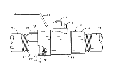
FIG. 1 is a side view of a valve constructed pursuant to
this invention, with a portion of the body joint being shown in
cross-section.
FIG. 2 is an end view of the body joint end of the valve
of FIG. 1 with the pipe at that end of the valve removed.
FIG. 3 is a view similar to FIG. 1 showing the body joint
portion, with the lip deformed against the adapter.
FIG. 4 is an end view of the structure as formed in FIG.
3 with the pipe removed.
DescriPtion of the Preferred ~mhodiment
Referring to the drawings in detail, and particularly
FIG. 1, reference character 10 generally designates a valve
constructed pursuant to this invention. The valve 10 comprises a
body 12 cont~;n;ng the usual valve member and seats (not shown),
with a valve stem 14 extending through the side wall of the body
12. A handle 16 is suitably secured on the valve stem 14 and is
employed for turning the valve stem 14, and hence the valve member
to open and close the valve. The valve 10 also normally includes
a stop pin 18 positioned to engage the handle 16 and control the
amount of turning of the valve stem 14.
The valve 10 is of the type for being threadedly
connected to adjacent pipe sections 20 and 22. Normally, the pipe

2146081
-


section 22 is threaded directly into the respective end 24 of the
valve body 12; whereas the pipe section 20 is connected to the
respective end 26 of the valve body 12 by means of an adapter 28.
The inner diameter of the end 26 of the valve body is larger than
the inner diameter of the end 24, such that the internal components
of the valve 10 can be installed through the end 26 and then held
in position with the adapter 28. The combination of the adapter 28
and the end 26 of the valve body 12 is normally referred to as a
"threaded body joint". It will also be observed that the adapter
10 28 is provided with a series of wrench flats 30 circumscribing the
head portion 31 of the adapter, by means of which the adapter 28
can be threaded into and from the body 12.
Pursuant to the present invention, the internally
threaded bore 3 2 at the end 26 of the body 12 is provided with a
counterbore 34, forming a lip 36 surrounding the adjacent head
portion 31 of the adapter 28. In other words, the adapter 28 is
sized to be threaded into the end 26 of the-body 12 until the head
portion 31 abuts the end of the counterbore 34. As shown in FIGS.
3 and 4, the lip 36 is of such a size that it can be deformed
radially inwardly to engage the wrench flats 30 of the adapter 28.
With this arrangement, the adapter 28 will be secured in the valve
body 12 against normal unthreading forces. ~owever, if access to
the inside of the valve 10 is required, what may be considered an
excessive force can be applied to unthread the adapter 28 and at
least partially deform the lip 36 back out toward the position
shown in FIG. 1. When the lip 36 is deformed inwardly as shown in


21~6081

FIGS. 3 and 4, the valve 10 may be unthreaded from the pipe section
22, for example, for whatever -'-eason, and the adapter 28 will be
maintained in secure connection with the valve-body. For example,
if there is pressure on the pipe section 20 and the valve 10 is
closed, the pipe section 22 can be unthreaded from the valve
without disturbing the adapter 28 and without fear of leakage from
the pipe section 20.
In the event the adapter 28 is forcibly unthreaded from
the body 12 by deformation of the lip 36 back out toward the
position shown in FIGS. 1 and 2, the adapter can again be threaded
back into the body section and the lip 36 again deformed against
the outer periphery of the adapter into contact with the wrench
flats 30.
Changes may be made in the combination and arrangement of
the parts and elements or steps and procedures set forth herein
without departing from the spirit and scope of the invention as
defined in the following claims.


Dessin représentatif
Une figure unique qui représente un dessin illustrant l'invention.
États administratifs

Pour une meilleure compréhension de l'état de la demande ou brevet qui figure sur cette page, la rubrique Mise en garde , et les descriptions de Brevet , États administratifs , Taxes périodiques et Historique des paiements devraient être consultées.

États administratifs

Titre Date
Date de délivrance prévu 1998-08-04
(22) Dépôt 1995-03-31
Requête d'examen 1995-03-31
(41) Mise à la disponibilité du public 1995-12-04
(45) Délivré 1998-08-04
Expiré 2015-03-31

Historique d'abandonnement

Il n'y a pas d'historique d'abandonnement

Historique des paiements

Type de taxes Anniversaire Échéance Montant payé Date payée
Le dépôt d'une demande de brevet 0,00 $ 1995-03-31
Enregistrement de documents 0,00 $ 1995-10-12
Taxe de maintien en état - Demande - nouvelle loi 2 1997-04-01 100,00 $ 1997-02-14
Taxe de maintien en état - Demande - nouvelle loi 3 1998-03-31 100,00 $ 1998-02-20
Taxe finale 300,00 $ 1998-03-23
Taxe de maintien en état - brevet - nouvelle loi 4 1999-03-31 100,00 $ 1999-02-22
Taxe de maintien en état - brevet - nouvelle loi 5 2000-03-31 150,00 $ 2000-02-23
Taxe de maintien en état - brevet - nouvelle loi 6 2001-04-02 150,00 $ 2001-04-02
Taxe de maintien en état - brevet - nouvelle loi 7 2002-04-01 150,00 $ 2002-03-05
Taxe de maintien en état - brevet - nouvelle loi 8 2003-03-31 150,00 $ 2003-01-29
Enregistrement de documents 50,00 $ 2003-08-14
Taxe de maintien en état - brevet - nouvelle loi 9 2004-03-31 200,00 $ 2004-03-05
Taxe de maintien en état - brevet - nouvelle loi 10 2005-03-31 250,00 $ 2005-02-08
Taxe de maintien en état - brevet - nouvelle loi 11 2006-03-31 250,00 $ 2006-02-13
Taxe de maintien en état - brevet - nouvelle loi 12 2007-04-02 250,00 $ 2007-02-16
Taxe de maintien en état - brevet - nouvelle loi 13 2008-03-31 250,00 $ 2008-03-28
Taxe de maintien en état - brevet - nouvelle loi 14 2009-03-31 250,00 $ 2009-03-27
Taxe de maintien en état - brevet - nouvelle loi 15 2010-03-31 450,00 $ 2010-03-24
Taxe de maintien en état - brevet - nouvelle loi 16 2011-03-31 450,00 $ 2011-02-25
Taxe de maintien en état - brevet - nouvelle loi 17 2012-04-02 450,00 $ 2012-02-07
Taxe de maintien en état - brevet - nouvelle loi 18 2013-04-02 450,00 $ 2012-10-16
Taxe de maintien en état - brevet - nouvelle loi 19 2014-03-31 450,00 $ 2013-11-04
Titulaires au dossier

Les titulaires actuels et antérieures au dossier sont affichés en ordre alphabétique.

Titulaires actuels au dossier
BALCOR HOLDING CORPORATION
Titulaires antérieures au dossier
BALON CORPORATION
SCARAMUCCI, JOHN P.
Les propriétaires antérieurs qui ne figurent pas dans la liste des « Propriétaires au dossier » apparaîtront dans d'autres documents au dossier.
Documents

Pour visionner les fichiers sélectionnés, entrer le code reCAPTCHA :


Pour visualiser une image, cliquer sur un lien dans la colonne description du document. Pour télécharger l'image (les images), cliquer l'une ou plusieurs cases à cocher dans la première colonne et ensuite cliquer sur le bouton "Télécharger sélection en format PDF (archive Zip)" ou le bouton "Télécharger sélection (en un fichier PDF fusionné)".

Liste des documents de brevet publiés et non publiés sur la BDBC .

Si vous avez des difficultés à accéder au contenu, veuillez communiquer avec le Centre de services à la clientèle au 1-866-997-1936, ou envoyer un courriel au Centre de service à la clientèle de l'OPIC.


Description du
Document 
Date
(yyyy-mm-dd) 
Nombre de pages   Taille de l'image (Ko) 
Dessins représentatifs 1998-07-28 1 7
Page couverture 1996-03-20 1 13
Abrégé 1995-12-04 1 9
Description 1995-12-04 4 143
Revendications 1995-12-04 3 57
Dessins 1995-12-04 2 29
Page couverture 1998-07-28 1 30
Taxes 2001-04-02 1 30
Taxes 2000-02-23 1 30
Correspondance 1998-03-23 1 50
Taxes 2003-01-29 1 31
Cession 2003-08-14 3 77
Taxes 1999-02-22 1 28
Taxes 2002-03-05 1 31
Demande d'entrée en phase nationale 1995-03-31 6 266
Correspondance de la poursuite 1995-03-31 3 132
Taxes 1998-02-20 1 32
Taxes 2004-03-05 1 31
Taxes 2005-02-08 1 27
Taxes 2006-02-13 1 26
Taxes 2007-02-16 1 28
Taxes 2008-03-28 1 32
Taxes 2009-03-27 1 37
Taxes 2010-03-24 1 34
Taxes 2011-02-25 1 34
Taxes 1997-02-14 1 45