Language selection

Search

Patent 2156462 Summary

Third-party information liability

Some of the information on this Web page has been provided by external sources. The Government of Canada is not responsible for the accuracy, reliability or currency of the information supplied by external sources. Users wishing to rely upon this information should consult directly with the source of the information. Content provided by external sources is not subject to official languages, privacy and accessibility requirements.

Claims and Abstract availability

Any discrepancies in the text and image of the Claims and Abstract are due to differing posting times. Text of the Claims and Abstract are posted:

  • At the time the application is open to public inspection;
  • At the time of issue of the patent (grant).
(12) Patent: (11) CA 2156462
(54) English Title: LIQUID CONTAINING AND DISPENSING PACKAGE
(54) French Title: CONDITIONNEMENT SOUS RECIPIENT DISTRIBUTEUR DE LIQUIDE
Status: Deemed expired
Bibliographic Data
(51) International Patent Classification (IPC):
  • B65D 41/26 (2006.01)
  • B65D 47/06 (2006.01)
  • B65D 47/12 (2006.01)
  • B65D 51/24 (2006.01)
(72) Inventors :
  • HAFFNER, EUGENE F. (United States of America)
  • RIOS, LUZ (United States of America)
(73) Owners :
  • KUBETECH CUSTOM MOLDING, INC. (United States of America)
(71) Applicants :
  • OWENS-ILLINOIS CLOSURE INC. (United States of America)
(74) Agent: GOWLING WLG (CANADA) LLP
(74) Associate agent:
(45) Issued: 2004-11-23
(22) Filed Date: 1995-08-18
(41) Open to Public Inspection: 1996-02-26
Examination requested: 1999-09-29
Availability of licence: N/A
(25) Language of filing: English

Patent Cooperation Treaty (PCT): No

(30) Application Priority Data:
Application No. Country/Territory Date
08/295,964 United States of America 1994-08-25

Abstracts

English Abstract

A liquid dispensing fitment for use on a container having a neck comprises a plastic body which has an inner wall defining an axial spout extending from within the neck of a container and axially beyond the end of the neck. The body has an outer annular wall spaced from the spout and connected to the spout by an integral annular connecting portion. The spout extends axially beyond the outer wall and has an upper generally C-shaped cross section defining an opening and a lower annular cross section. The annular connecting portion is inclined with respect to the axis of the spout and has its lowermost portion aligned with the opening of said C-shaped portion of said spout. The outer wall has an axial opening extending from a position aligned with the juncture of the C-shaped portion and annular portion of the spout through the annular connecting portion to define a combined drain back opening and a near empty pour out hole. The fitment is provided with means on the upper end of the outer wall for engaging the neck of the container. The lower portion of the spout is substantially smooth in an axial direction to facilitate drain back. The lower portion of the spout has an inner surface formed with an integral axial rib aligned with the axial opening in the outer wall to facilitate manufacture. The wall of the fitment is provided with an axially extending opening that extends from a position aligned with the junction of the C-shaped portion and annular portion to define a combined drain back opening and near empty pour out hole.


French Abstract

Un assemblage de distribution liquide pour une utilisation sur un récipient ayant un embout comprenant un corps en plastique muni d'une paroi interne définissant un bec axial s'étendant de l'embout d'un récipient et axialement au-delà de l'extrémité de l'embout. Le corps possède une paroi annulaire externe éloignée du bec et reliée au bec par une partie de raccordement annulaire intégrale. Le bec s'étend axialement au-delà de la paroi externe et a une section transversale supérieure généralement en forme de C définissant une ouverture et une section annulaire inférieure. La partie de raccordement annulaire est inclinée par rapport à l'axe du bec et a sa partie la plus inférieure alignée avec l'ouverture de ladite partie en forme de C dudit bec. La paroi externe a une ouverture axiale s'étendant d'une position alignée sur la jonction de la partie en forme de C et de la partie annulaire du bec à travers la partie de raccordement annulaire pour définir à la fois une ouverture arrière de drain et un orifice de déversement presque vide. L'assemblage est doté de moyens sur l'extrémité supérieure de la paroi externe permettant d'engager l'embout du récipient. La partie inférieure du bec est substantiellement lisse dans une direction axiale pour faciliter le retour de l'écoulement. La partie inférieure du bec a une surface interne formée d'une nervure axiale intégrale alignée avec l'ouverture axiale dans la paroi externe pour faciliter la fabrication. La paroi de l'assemblage est pourvue d'une ouverture selon l'axe de son extension qui s'étend depuis une position alignée sur la jonction de la partie en forme de C et de la partie annulaire pour définir à la fois une ouverture d'écoulement arrière et un orifice de déversement presque vide.

Claims

Note: Claims are shown in the official language in which they were submitted.


The embodiments of the invention in which an
exclusive property or privilege is claimed are defined
as follows:

1. A liquid dispensing fitment for a container
having a neck, said fitment comprising:
a plastic body,
said body having an inner wall defining an
axial spout extending from within the neck of said
container and axially beyond an end of the neck,
said body having an outer annular wall spaced
from said spout and connected to said spout by an
integral annular connecting portion,
said spout extending axially beyond said
outer wall,
said spout having an upper, generally C-
shaped portion, C-shaped in cross-section, defining an
opening and a lower annular portion,
said annular connecting portion being
inclined with respect to the axis of the spout and
having its lowermost portion aligned with the said
opening of said C-shaped portion of said spout,
said outer wall having an axial opening
extending from a position aligned with the juncture of
the C-shaped portion and annular portion of the spout
through said annular connecting portion to define a
combined drain back opening and a near empty pour out
hole, and
integral means on an upper end of said outer
wall for engaging the neck of said container,
said lower annular portion of said spout
being substantially smooth in an axial direction to
facilitate drain back,


-8-


said lower annular portion of said spout
having an inner surface formed with an integral axial
rib having an unsymmetrical cross section aligned with
said axial opening in said outer wall to facilitate
manufacture.

2. The liquid dispensing fitment set forth in
claim 1, wherein the neck of said container has a
finish, and said fitment is positioned in said finish
with said integral means engaging said neck to define a
liquid dispensing package.

3. The liquid dispensing fitment set forth in
claim 2, further including a closure having means
thereon for engaging said finish of said container.

4. A liquid dispensing package comprising
a container having a hollow body and a neck
with a finish having an upper surface with external
threads and an internal surface,
a fitment comprising a plastic body,
said body having an inner wall defining an
axial spout extending from within the neck of said
container and axially beyond an end of the neck,
said body having an outer annular wall spaced
from said spout and connected to said spout by an
integral annular connecting portion,
said spout extending axially beyond said
outer wall,
said spout having an upper, generally C-
shaped portion, C-shaped in cross-section, defining an
opening and a lower annular portion;
said annular connecting portion being
inclined with respect to the axis of the spout and
having its lowermost portion aligned with the said
opening of said C-shaped portion of said spout,


-9-


said outer wall having an axial opening
extending from a position aligned with the juncture of
the C-shaped portion and annular portion of the spout
through said annular connecting portion at a lowest
point of said annular connecting portion to define a
combined drain back opening and a near empty pour out
hole,
said outer annular wall having an upper end
and a portion adjacent said upper end,
said portion of said outer annular wall
adjacent said upper end of said outer annular wall
having an outer surface engaging the internal surface
of said finish of said container,
said axial opening in said outer annular wall
extending within said finish beyond said body of said
container to said portion engaging an inner surface of
said finish such that substantially the entire contents
can be dispensed,
said lower annular portion of said spout
having an inner surface formed with an integral axial
rib having an unsymmetrical cross section aligned with
said axial opening in said outer wall to facilitate
manufacture,
integral means on said upper end of said
outer wall for engaging a portion of the upper surface
of the finish adjacent the inner surface of the finish
on the neck of said container

5. The liquid dispensing package set forth in
claim 4 wherein said integral means on said upper end
of said outer wall comprises an integral flange
engaging a portion of the upper surface of said finish
adjacent the internal surface of said finish.


-10-


6. The liquid dispensing package set forth in
claim 5 including a plastic closure, said plastic
closure including a top wall and a peripheral wall
extending downwardly within the inner wall and outer
wall, said closure including an annular wall extending
radially outwardly intermediate ends of said peripheral
wall and an annular skirt extending downwardly and
having internal threads engaging said external threads
on said finish, said annular wall having an integral
sealing bead engaging said integral flange on said
upper end of said outer wall of said fitment.


-11-

Description

Note: Descriptions are shown in the official language in which they were submitted.


16560 USA
LIQOID CONTAINING AND DISPENSING PACKAGE
This invention relates to liquid containing and
dispensing packages and particularly to such packages which
include a pouring spout and a closure that functions as a
measuring cup.
BackQronnd and Su~ary of the Invention
In one type of liquid dispensing package, a pouring
spout fitment is positioned on the neck of the container and a
closure in the form of the cup is interengaged with the periphery
of the container. More specifically, a spout is mounted in a
first fitment that is on a container. The fitment has internal
threads which are engaged by the external threads of a cover.
In United States Patent 4,706,829, there is disclosed
a liquid containing and dispensing package comprising a hollow
plastic container having a neck, a fitment interengaging the
neck and a closure. The fitment interengages the neck and as
a f first peripheral portion extending axially and having a portion
defining a spout having a pouring lip extending axially inwardly
of the end of the neck, and a closure comprising a top wall and
a first peripheral wall extending from the top wall axially
inwardly. The closure includes a radial portion extending from
the peripheral wall and sealingly engaging an annular area of
the fitment. The closure defines a dispensing cup and includes


~1~4
a second outer peripheral wall spaced from the first peripheral
wall which has internal threads engaging external threads on
the neck of the container.
Among the objectives of the present invention are to
provide a liquid containing package wherein the spout fitment
or insert has improved mold ability in larger size spouts; which
requires less complicated tooling such that is easier to mold.
In accordance with the invention, a liquid dispensing
fitment for use on a container having a neck comprises a plastic
body which has an inner wall defining an axial spout extending
from within the neck of a container and axially beyond the end
of the neck. The body has an outer annular wall spaced from
the spout and connected to the spout by an integral annular
connecting portion. The spout extends axially beyond the outer
wall and has an upper generally C-shaped cross section defining
an opening and a lower annular cross section. The annular
connecting portion is inclined with respect to the axis of the
spout and has its lowermost portion aligned with the opening
of said C-shaped portion of said spout. The outer wall has an
axial opening extending from a position aligned with the juncture
of the C-shaped portion and annular portion of the spout through
the annular connecting portion to define a combined drain back
opening and a near empty pour out hole. The f itment is provided
with means on the upper end of the outer wall for engaging the
neck of a container. The lower portion of the spout is
substantially smooth in an axial direction to facilitate drain
back. The lower portion of the spout has an inner surface
-2-


formed with an integral axial rib aligned with the axial opening
in the outer wall to facilitate manufacture. The wall of the
fitment is provided with an axially extending opening that
extends from a position aligned with the junction of the C-
shaped portion and annular portion to define a combined drain
back opening and near empty pour out hole.
-3-


Description of the Drawings
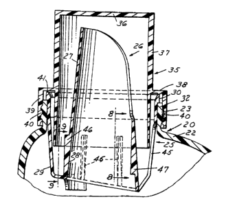
FIG. 1 is a sectional view of a liquid containing and
dispensing package embodying the invention.
FIG. 2 is a bottom plan view of the f itment in the
package.
FIG. 3 is a top plan view of the fitment.
FIG. 4 is a front elevational view of the fitment as
viewed from the right in FIG. 1.
FIG. 5 is a fragmentary sectional view taken along
the line 5-5 in FIG. 3.
FIG. 6 is an elevational view of the f itment as viewed
from the left in FIG. 1.
FIG. 7 is a fragmentary view on an enlarged scale of
the lower portion of the fitment shown in FIG. 5.
FIG. 8 is a fragmentary sectional view taken along
the line 8-8 in FIG. 1.
FIG. 9 is a fragmentary sectional view taken along
the line 9-9 in FIG. 1.
FIG. 10 is a fragmentary sectional view on an enlarged
scale of a portion of the upper edge of the fitment.
-4-

CA 02156462 2004-02-18 ~' '~
Description of the Preferred Embodiments
In accordance with the invention, the container
package 20 comprises a hollow plastic container having a
body 22 and a neck 32. The neck 32 ~is formed with external
threads 23 . The package 20 further includes a f itment or insert
25 that comprises a centrally disposed inner spout portion 26
that has an arcuate upper portion 27 which is generally C-shaped
in transverse cross-section. The spout 26 has an annular lower
portion 28. The fitment 25 further includes an outer wall
portion 29 interconnected by an annular portion and extending
generally upwardly and outwardly. The outer wall portion 29
further includes a peripheral flange 30 adapted to engage the
upper surface of the neck 32.
The package 20 further includes a.closure 35 that
is generally cylindrical including a top wall 36 and a peripheral
wall 37. The peripheral wall 37 extends downwardly within the
walls of the spout 26. The cap 35 further includes an annular
wall 38 extending radially outwardly intermediate the ends of
the peripheral wall 3? and an annular axial skirt 39 extending
downwardly and having internal threads 40 engaging the external
threads 23 on the neck 32.
The wall 38 of the closure includes an annular
downwardly extending annular projection in the form of a bead
41, preferably having a V cross-section, that engages the fitment
25 to provide a primary seal between the closure 35 and the
fitment 25 and, in turn, force the fitment 25 against the end'
of the neck 32.
-5-


CA 02156462 2004-02-18
The container may be made of plastic material such
as high density polyethylene. The fitment 25 may be made of
other plastic materials, for example, low density polyethylene.
The closure 35 may be made of plastic material such as
polypropylene.
The wall of the fitment is provided with an axially
extending opening or slot 45 that extends from a position aligned
with the junction of the C-shaped portion and annular portion
to define a combined drain back opening and near empty pour out
hole.
Unlike earlier pour spouts or fitments 25, where the
drain and near empty holes are separate, this spout or fitment
25 has one continuous, uninterrupted slot, which is a combination
of the earlier drain and near empty holes. By combining these
two individual features into one, the tooling used to manufacture
the spout is simplified, and the component is easier to produce
as well.
The drain back and near-empty holes remain separate,
but by including a chamfer or recess at the base of the near-
empty hole, the design will allow the tooling to also be
simplified, as there would be only positive taper surfaces in
the direction of draw.
Thefitment 25further includescircum~erential spaced
vertical ribs 46 on the outer surface of the lower portion 28
(FIGS. 5, 9) and a single vertical rib 47 on the inner surface
of the lower portion 28 opposite the opening 45.
-6-


y' The vertical ribs 46 facilitate stacking of the
fitments. First, after the parts are manufactured, they are
stacked one on top of the other, about twenty (20) high. These
stacks are then placed on their side in the shipping cartons,
and multiple stacks laid upon each other. This method of
packaging greatly improves the efficiency of the cartons. The
vertical rib 46 prevents the spouts in stacks from being
compressed too much. If the vertical ribs were not included
as shown, the parts which have multiple tapered surfaces, could
be stacked so tightly together, that the equipment used to pick
and place the spouts into the container would malfunction. The
function of the rib 47 is utilized with the machinery used to
place the spout.
In particular, the single, unsymmetrical rib 46 is
used for orienting the spout relative to the container, so that
the spout's front pouring edge is placed towards the front
cbntainer, opposite of the handle of the container.
It can thus be seen that there has been provided a
liquid dispensing package wherein the spout fitment or insert
has improved mold ability in larger size spouts; which inquires
less complicated tooling such that is easier to mold.

Representative Drawing
A single figure which represents the drawing illustrating the invention.
Administrative Status

For a clearer understanding of the status of the application/patent presented on this page, the site Disclaimer , as well as the definitions for Patent , Administrative Status , Maintenance Fee  and Payment History  should be consulted.

Administrative Status

Title Date
Forecasted Issue Date 2004-11-23
(22) Filed 1995-08-18
(41) Open to Public Inspection 1996-02-26
Examination Requested 1999-09-29
(45) Issued 2004-11-23
Deemed Expired 2014-08-19

Abandonment History

There is no abandonment history.

Payment History

Fee Type Anniversary Year Due Date Amount Paid Paid Date
Application Fee $0.00 1995-08-18
Registration of a document - section 124 $0.00 1995-11-09
Maintenance Fee - Application - New Act 2 1997-08-18 $100.00 1997-06-26
Maintenance Fee - Application - New Act 3 1998-08-18 $100.00 1998-06-30
Maintenance Fee - Application - New Act 4 1999-08-18 $100.00 1999-07-06
Request for Examination $400.00 1999-09-29
Maintenance Fee - Application - New Act 5 2000-08-18 $150.00 2000-06-23
Maintenance Fee - Application - New Act 6 2001-08-20 $150.00 2001-07-11
Maintenance Fee - Application - New Act 7 2002-08-19 $150.00 2002-06-26
Maintenance Fee - Application - New Act 8 2003-08-18 $150.00 2003-06-20
Maintenance Fee - Application - New Act 9 2004-08-18 $200.00 2004-07-13
Final Fee $300.00 2004-09-03
Maintenance Fee - Patent - New Act 10 2005-08-18 $250.00 2005-07-08
Maintenance Fee - Patent - New Act 11 2006-08-18 $250.00 2006-07-07
Maintenance Fee - Patent - New Act 12 2007-08-20 $250.00 2007-07-04
Registration of a document - section 124 $100.00 2008-06-10
Maintenance Fee - Patent - New Act 13 2008-08-18 $250.00 2008-07-15
Maintenance Fee - Patent - New Act 14 2009-08-18 $250.00 2009-07-13
Maintenance Fee - Patent - New Act 15 2010-08-18 $450.00 2010-07-15
Maintenance Fee - Patent - New Act 16 2011-08-18 $450.00 2011-08-01
Maintenance Fee - Patent - New Act 17 2012-08-20 $450.00 2012-07-30
Registration of a document - section 124 $100.00 2014-05-26
Owners on Record

Note: Records showing the ownership history in alphabetical order.

Current Owners on Record
KUBETECH CUSTOM MOLDING, INC.
Past Owners on Record
HAFFNER, EUGENE F.
OWENS-ILLINOIS CLOSURE INC.
REXAM CLOSURE SYSTEMS INC.
REXAM CONSUMER PLASTICS INC.
RIOS, LUZ
Past Owners that do not appear in the "Owners on Record" listing will appear in other documentation within the application.
Documents

To view selected files, please enter reCAPTCHA code :


To view images, click a link in the Document Description column. To download the documents, select one or more checkboxes in the first column and then click the "Download Selected in PDF format (Zip Archive)" or the "Download Selected as Single PDF" button.

List of published and non-published patent-specific documents on the CPD .

If you have any difficulty accessing content, you can call the Client Service Centre at 1-866-997-1936 or send them an e-mail at CIPO Client Service Centre.


Document
Description 
Date
(yyyy-mm-dd) 
Number of pages   Size of Image (KB) 
Representative Drawing 1998-04-23 1 21
Cover Page 2004-10-20 1 55
Claims 1999-11-22 4 135
Cover Page 1996-04-17 1 16
Abstract 1996-02-26 1 39
Description 1996-02-26 7 208
Claims 1996-02-26 4 117
Drawings 1996-02-26 3 104
Description 2001-02-18 7 213
Drawings 2001-02-18 3 104
Claims 2001-02-18 4 132
Representative Drawing 2004-03-24 1 14
Correspondence 2004-09-03 1 32
Assignment 1995-08-18 6 264
Prosecution-Amendment 1999-09-29 1 38
Correspondence 1995-10-10 7 208
Prosecution-Amendment 1999-11-30 1 26
Prosecution-Amendment 2003-08-21 3 119
Prosecution-Amendment 2004-02-18 10 369
Assignment 2008-06-10 6 170
Assignment 2014-05-26 15 363